All posts by Gerhard Marx

Psychiatrist and Woodworker

Bandsaw Mitre-sled

I am in the process of building a series of wooden handplanes. Due to the fact that I cannot buy timber in dimensions that would allow construction from a single piece, I have to follow the method of laminating made famous by James Krenov. Unfortunately, this necessitates a fairly functional bandsaw given the dimensions of these planes. My bandsaw is of a Chinese persuasion that few people peregrinating the so called western world (including myself) would have heard of before. I always though that was how a bandsaw should look like as I have never seen another until I started reading a bit more about woodwork.

Every expert these days seems to advocate for using the bandsaw in a way that the table saw used to be in years gone by. I first thought they were mad as my bandsaw could not even cut a smooth curve leave alone rip and re-saw and all these absurd new tasks they suggested should be done with it. Then I had a look at how these bandsaws looked like and realised that they were quite a bit different to mine. In the first place, the operators actually tuned the contraption before going to war with it. I did not even know that it could be tuned. I then watched a video by Michael Fortune on how to do this. It is on the Fine Woodworking website (member’s section if I remember correctly).

Anyway, this is all a bit besides the point. Point is, I spent a significant part of a week on rehabilitating my bandsaw, which included the process of building this jig that I call a “Bandsaw Mitre-sled”. I plan to write a post on the actual rehab process of the bandsaw in the near future.

The owner of a local tool shop by the name of Martin Mozny (Windhoek Tool Centre) gave me a whole heap of Festool equipment that was apparently used for demonstrations and therefore not in a condition to be sold as new. Despite this the stuff is in top order, especially for building jigs. While contemplating the design of this jig I consulted the container that house the orphan Festool bits and pieces. I considered both of the parts in the below pictures, but decided to rather use another.

IMG_7033IMG_7034

Here you can see the the mitre gauge I decided on together with a piece of scrap plywood that would become the main parts of the jig.

IMG_7035

Next I found some scrap pine and swarthout (not in the picture) to form the edges/aprons. A strip of Harde Peer left over from another job was shaped first on the table saw, then the thicknesser and finally handplaned to fit perfectly in the channel/dado in the bandsaw table.

IMG_7036IMG_7037

Here you can see how I have set up a temporary fence to drill the holes for attaching the strip of Harde Peer and the Festool mitre gauge. The strip was then glued and screwed to the plywood.

IMG_7042IMG_7043IMG_7044IMG_7060

In the pictures below you can see the profile of the aluminum arm of the mitre gauge. The bottom of the profile is fairly thick, which allowed me to drill 5 mm holes in order to cut thread for a 6 mm bolt.

IMG_7038IMG_7039IMG_7040IMG_7041

Here you can see how I drilled the holes on the drill press …

IMG_7049IMG_7050IMG_7051IMG_7053IMG_7052

… and cutting the thread.

IMG_7054IMG_7055IMG_7057IMG_7058

The mitre gauge was then fixed to the plywood with three countersink bolts.

IMG_7061IMG_7062

As you can see these bits of scrap pine has done duty in several other incarnations. The swarthout in the centre had less battle scars. I then processed these pieces to assume the same dimensions.

IMG_7064

In the first picture below you can see how I removed a small area of the swarthout to accept the harde peer strip. I also used dividers to quickly mark out all the screw holes that needed to be drilled in the plywood to attach the sides/aprons.

IMG_7065IMG_7066

After drilling the mentioned holes I clamped the sides and plywood into place as shown. In the third picture you can see how useful a cuff can be to restrict the depth of the pilot hole to exactly the length of the screw.

IMG_7067IMG_7068IMG_7069IMG_7070

The next step was to tidy up the wooden parts of the jig. Yes, you are right I did remove the mitre gauge to make this a bit easier. You can also see how handy my “Proletarian Sanding” Contrivances are in these situations. You will find an entire post devoted to the building of these sanding planes, under the category Handtools.

IMG_7071IMG_7072IMG_7073

The mitre gauge goes back and the jig is ready to cut the zero clearance curve …

IMG_7074IMG_7075

… like so …

IMG_7078IMG_7079IMG_7080IMG_7081

The first cut I made using this jig was a 51º bedding angle on a blank meant to become a small smoothing plane. It was made up of Beech with an Ysterhout sole. One unexpected advantage of this jig I discovered was that the zero clearance curve tells you exactly where the cut will be made. If for example you mark it out on the stock as I did on the plane blank, it becomes extremely easy to position the stock for a perfect cut …

IMG_7146IMG_7147IMG_7148IMG_7149

… as shown in the pictures below.

IMG_7150IMG_7151IMG_7152IMG_7153

My journey 4

In this edition of my journey I would like to write a bit about where I am in my woodworking in terms of what I am busy with and how I want to approach it from a philosophical point of view. My approach is clearly changing as the years go by so I thought it would be good to document it from time to time, in order to look back and put it all in perspective somewhere down the line.

For the past 2 years I have been busy setting up a functional workshop and I estimate that this phase of predominantly working on the shop (rather than making furniture) will take at least another 2-3 years. It might well sound ridiculous to other woodworkers, but woodworking is a leisure pastime for me and I do not have that much of it. I do not have to produce heaps of stuff to enjoy the process and the last thing I want is to feel pressured to get a heap of stuff done similar to my day job.

Therefore I am progressing slowly and trying to consciously savor the time in the shop purely for being there rather than what I produce while I am there. I know a lot of people say one should try to build furniture as much as possible while in the shop, but I enjoy the challenge of building and restoring tools as much, if not more. When I feel that my shop is setup in a way that would make the next step (of building furniture) enjoyable, I will move on.

What I am finding is that the process of building tools and shop structures is giving me an opportunity to hone my skills on stuff that is less important to get perfect, which is not what I want to do while building furniture. The issue here is that although I have always known that woodwork is my thing, I have not been able to do much due to the career path I have chosen. Therefore I am a real novice and has no proper training to fall back on. It is only now that I am starting to read and learn about the finer points of this wonderful craft. This is another reason why I am happy to spend another 2 years working on the shop, as the learning curve in terms of practical skills takes time and my shop time is limited. Another advantage of going about it this way is that I am able to figure out what type of bench and other paraphernalia works for me before jumping into the fray of proper cabinet making.

If we then move on to how I want to approach the phase of building predominantly furniture. My philosophical stance has a lot to do with how I feel about the wood I work with. As I explained in “My journey 3” I feel a certain responsibility to produce timeless pieces, whether that is tools or furniture, out of sheer respect for the forest, it’s history and how it ties up with the history of my own ancestors. This might sound a bit fluffy, but I do not feel the need to justify myself in this respect.

In terms of the above, it is much easier to produce a timeless piece while building tools as I will be able to use and enjoy the tool more often than a piece of furniture. I also see these tools as heirlooms that could stay in the family for a long time after I pass on and so attain that timeless status in another way. Since reading lots of old (mostly late 19th century) woodwork books it is surprising how little has changed in terms of the design and use of especially handtools. Hence my view of this pursuit as a shortcut towards timeless products. If you are interested in getting hold of these old books, go to the library page on this website and you will find two links to websites where one can download heaps of these books for free.

In the meantime I am trying to read and learn as much as possible about design to prepare for the next phase which will be far more challenging.

PVA glue bottle tip

I got sick of filling a small PVA glue bottle from the 5 liter bucket as it is messy and takes up time that can be spent working wood. A few weeks ago I noticed that the nozzle of  the dishwashing liquid sold around these parts has the same design as a Gorilla glue bottle. This design works very well to keep the nozzle from becoming stuck with hard glue. On the local PVA glue bottles you find a screw-top that is impossible to open after a few glue-ups. The 1.5 liter bottle helps to make the refills few and far in between. You can seen the PVA glue bucket I emptied in the dishwashing bottle sitting in the basin filled with water so that it would be easier to clean.

IMG_7129IMG_7130

In the last few pictures you can see what I mean with the design of the nozzle. It is very easy to use and does not necessitate lots of meticulous cleaning to keep it functioning.

IMG_7131IMG_7132

Extremely Efficient Effulgent Arm (EEEA)

This post will document one of the easiest projects that can make a huge difference in your enjoyment of the craft as well as improve the accuracy and safety. My eyesight is deterioration with age so good lighting makes a significant difference when doing precise work. For this reason I decided to build an arm that can swing across my assembly table with a spot light and a power point.

I took some scrap angle iron and one of those hinges used in metal work. From this I welded a short arm and a part of the hinge became a hook that can be bolted to the wall to make the arm easy to remove.

100_0304100_0305

A quick coat of anti-rust paint and BYU (Bob’s your Uncle).

100_0309100_0308100_0307

In order to give the arm some more reach, I laminate some pieces of plywood as it is strong yet lightweight.

100_0306

Prior to shaping this part of the arm on the tablesaw I screwed another thin strip of plywood to it’s top section. This was meant to become the removable lid covering the electrical wires running inside.

100_0311100_0313

After the shaping process I cut the dado meant to house the wires. In the picture below you can see it with the lid unscrewed.

100_0314

Next I fitted a multi-plug to the side of the arm with it’s wire running in the dado as shown above.

100_0327100_0328100_0329

The multi-plug wire was connected with an extension inside the arm as shown.

100_0330100_0331100_0332

The extension was fitted with a plug at the hinge end of the arm. This design feature was again aimed at making it easy to remove the whole arm if I need to work on it or for some reason have to get it out of the way.

100_0334100_0335100_0336100_0337

Next I added a desk lamp to act as a spotlight on the extreme front of the arm. It is one of those that clamp (with an integral spring clamp) to the side of a desk or table. I screwed it on to keep the clamp available for another task. As you can see from the pictures it has it’s own switch and is plugged into the multi-plug.

100_0338100_0523

If one would to be able to look at this setup from the ceiling, the arm swings across the table with an arc similar to the crude drawing below. Therefore covering any particular area that is in need of enhanced lighting.

Boom arm swing

Then I added a small but bright fluorescent light to the bottom of the arm. Together with the spot light it really improves the lighting of a particular part of the assembly table by swinging it there. In the pictures below you can also see another function of the arm as provided by the spring clamp of the desk lamp. I took one of my Festool power-cords, plugged it in at the multi-plug and clamped it in the mentioned clamp. This way it is always in easy reach, yet completely out of the way.

IMG_6797IMG_6798


Finally, a few pictures to show how the Festool cord and multi-plug adds value. The nice thing about the Festool cord is that it fits all the Festool appliances. In my case a router, a Domino and a circular saw (as pictured).

100_0541100_0573100_0576

Darwinian Sawhorse

In this post I want to document what must be officially the longest time it took me to get to the current product. These four saw horses were first built in 1999 when we still lived in South Africa. Essentially they consist of two scrap Swarthout frames joined at the apex by a single full length piano hinge. The frames were glued and screwed together using simple lap joints as seen below. The legs are restricted from opening up too far by bits of rope. I stapled an old piece of carpet to the apex to soften it up a bit for finishing tasks.

lap joints

In these pictures you can appreciate one of the major advantages of these saw horses. They can be stored out of the way taking up very little shop space, which is often a problem with this must-have shop aid. You can see how I made two wooden (scrap pine) brackets that keep them sitting on the wall quite happily. As an added bonus you can appreciate my 4 year old daughter’s art.

IMG_6945IMG_6946

In the first picture below you can see them lined up in front of the shop were they do most of their work these days. From the next couple of pictures it might be more apparent what one of the weaknesses of this type of sawhorse is. As you can see they used to be the legs of my work surface until I built the workbench/assembly table. You will find a whole series of posts on this project under the category “Bench” if you are interested.

Anyway, the weakness mentioned has to do with the fact that there is nothing that prevents these sawhorses from closing up. This is especially a problem when any pressure  is applied square in relation to the sawhorse and horisontally to the top or workpiece they support. This can be very frustrating and unsafe depending on the activity.

IMG_6900100_0006100_0007

In order to solve the above problem while wanting to keep the advantage of the sawhorse’s storability, I made the objects below that I do not have a good name for. They simply drop over the frame forming the lower part of the legs and completely curbs the problem discussed above.

IMG_6899IMG_6902

The next modification was done at the same time as the above. One of the most common tasks I use these sawhorses for is to cut rough boards with my Festool TS 55 Cirlcular Saw into more manageable chunks. For this purpose I made these sacrificial beams to sit on top of the sawhorse. They are easy to install and remove and allows me to have the rough boards very stable on the sawhorses, while not having to worry about cutting into them.

IMG_6901IMG_6270

Stingy storage ideas

For this post I took a few pictures of very basic and quick ways of organising your shop in such a way that the bits and pieces you are looking for are easily accessible at no cost or cheap at worse. I plan to keep adding to this post to create a major opus over time so check in from time to time if you find this useful.

In this picture you can see how an old 20 liter paint bucket becomes the ideal storage for T-channels (used for jig-building predominantly), copper pipe (used to make the ferrule around handtool handles), long strips of wood, treaded rod, etc etc.

IMG_6790

In this picture it is obvious how see-through water bottles (2 liter in this case) can become the ideal storage for small bits of scrap wood, which I find very useful to have at hand. It seems that most of the experts advise woodworkers to chuck these away, but I really find a job for most of them. I simply cut the top of the bottle away with a carpet knife and you can probably appreciate how the fact that it is transparent helps to locate the piece you need.

IMG_6791

These plastic containers slide onto each other and it is fairly easy to grab the one you want and walk off to the location where you need the contents. If they are available to buy in Namibia, I assume they should be widely available. I store all my steel wood screws and bolts in these. The gibberish that you can not read is Afrikaans, my mother tongue.

IMG_6792100_0082IMG_6789

In the centre of the picture below you can see another function for smaller see-through water bottles. I store smaller bits of threaded rod, steel, leather, assorted bolts and nuts, etc etc in these.

IMG_6793

Empty tins of chopped tomatoes, become ideal storage for for shorter flat strips of wood that resembles spatulas for applying glue or mixing epoxy etc, etc.

IMG_6794

The same tins screwed to a vertical part of a storage cabinet with a single screw becomes an easily accessible dwelling for pencils, magic markers, drill bits, etc,etc.

IMG_6801

In this picture you can see how my main tool storage “cabinet” looks like. It is actually a slightly modified whip-up of the crates my Dad built to transport the tools he passed on to me, but that is a story for another day. The yellow cary-case for my DeWalt cordless drill is what I want to discuss. It has two handy drawers with dividers at the bottom and a tray with various drill bits that fit on top of these dividers. The problem is that you first need to remove the tray before you can access the dividers area. I took the trays out and positioned them on top of the case. The drawers with dividers now house heaps of drill bits, router bits, and thread cutting bits all within easy reach next to my bench.

IMG_6888IMG_6802IMG_6803

In the example below, a scrap piece of pine with holes drilled into it, quickly and parsimoniously took care of 23 different hand tools. In the first picture you can see how I made a few tests with a pair of compasses to work out were to drill a hole with a Forstner bit to leave enough of a gap to accept a wide chisel. As you can see that it accommodates 8 chisels, two marking gauges, two calipers, three dividers, several small triangular files, several awls, a Lie-Nielsen float and a Stanley multi-bit screwdriver. Best is, that there is space for a few more and all that from one crappy piece of pine.

IMG_6884IMG_6885IMG_6887IMG_6886IMG_6890


While we are on the topic of scrap pieces of wood, here is another idea to store your F-style clamps in a small area, yet very assessable. I took a piece of scrap plywood and used my Festool Domino to cut 5 mm wide and 15 mm deep slots on one edge. I guess you can achieve the same with a table saw or a router. The domino made it easy because it took one plunge with the 5 mm bit and Bob’s your Uncle. The piece of plywood was then screwed to the front edge of the cabinet’s side. The shafts of my Bessey F-style clamps fit snugly into these slots. Once in the slot one can the slide the clamp to the closed position and BYU.

IMG_5888IMG_6804


Sliding Deadman (with a twist)

As promised I will now write a post on how a sliding deadman could look like that toils in tandem with my “legvise with a twist”, while they are both attached to my “alternative workbench/assembly table”. There are posts on both these projects under the categories of “Bench accessories” and “Bench” respectively.

I built this deadman at the same time as the legvise, but concentrated more on the legvise towards the end of the project, finished it and went back to the deadman. I again used Assegaai predominantly with small pieces of Ysterhout, Witpeer and Kershout to make up the rest. In the picture below you can see the feral nature of the wood I work with. In order to make up stout chucks of lumber I always have to laminate petite pieces that are carefully liberated from the crude boards of wild wood. You can see the rough boards these pieces came from in the post on the legvise.

100_0326

In the next picture you can see how a tidied up version of the laminated piece in the previous picture receives a face of Assegaai. The reason for gluing the bigger piece together like this is in the first place to have a front that looks solid (rather than laminated), but also to created strength/stability (by means of glue lines) in different directions. Whether it actuals works like this I am not too sure, but it makes some sense to me. I guess only time will tell. Anyway, you should be able to see the piece of Ysterhout in the centre of the original laminated part flanked by Assegaai. The Ysterhout was available it the size needed (reason number one for inclusion) but was also included to enhance the strenghts of the beam.

100_0344100_0345

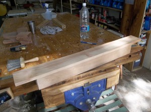
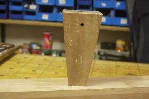
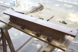
The blank that emerged after the clamps were removed was quite a bit more irregular in shape than what is apparent in the picture below.

100_0348

I managed to flatten and square it up by means of stoical hand planing over a few days of doing tolerable sessions at a time. This approach (despite not being the motivating reason for doing it this way) is probably the best one can hope for in terms of the result as the blank are allowed to settle after each minor release of tension.

100_0376100_1236

The sqaured-up product was quite pleasing to the eye and supplied a heartening sense of achievement.

100_1263100_1264

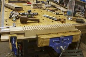
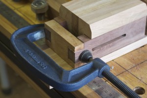
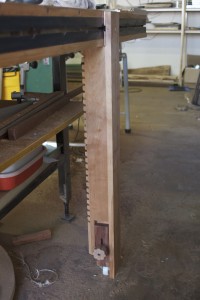
The next step was to router out a fairly large stopped dado that would accept the mechanism designed to easily adjust the height of the deadman.

IMG_5587IMG_5588IMG_5588

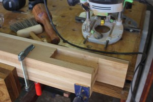
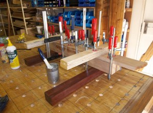
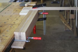
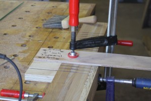
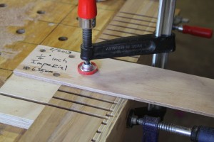
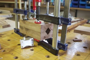
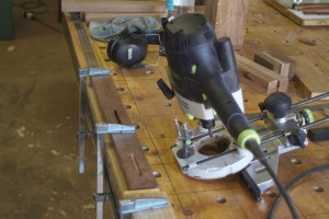
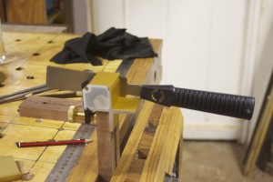
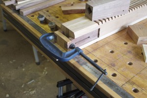
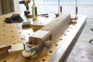
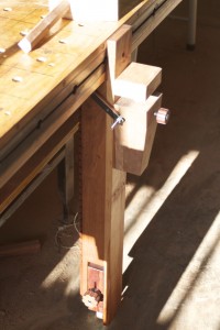
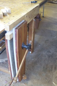
In the pictures below you can see how I simply used the F-style clamps hooked into the conveniently located T-channels along the side of my assembly table to fix the evolving deadman in order to locate the guiding jig (resembling a woodworking square) firmly on the table as well as the substrate. The advantage of using these jigs is that it shows you exactly where the dado will be cut in relation to the guiding edge.

IMG_5589IMG_5590

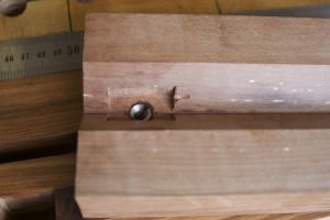
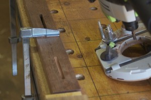
I made a further upgrade to the jig for the purpose of this particular assignment. You should be able to see the panel pin that I tapped into the stock of the guiding square located in the previous dado. This setup allows you to cut dados at exactly the same distance from each other without the need for any cumbersome measuring.

IMG_5591

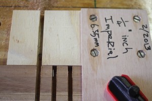
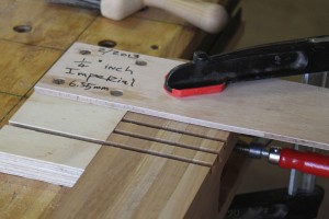
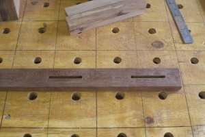
Despite my clever jig-adaptations this process took ages as each dado had to be cut twice to reach the decided depth. The dados are 6 mm wide (the width of the threaded rod meant to frequent it in the future of this contraption) and 12 mm deep. There is this rule of thumb that one should only cut to a maximum depth equivalent to the diameter of the straight router bit being used in a particular pass, hence the double pass strategy.

IMG_5598IMG_5599

After such an endeavor it is usually advisable to take a moment to savour what you have accomplished before moving onwards and upwards.

IMG_5600IMG_5601

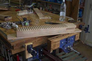
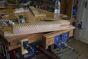
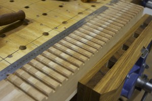
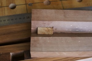
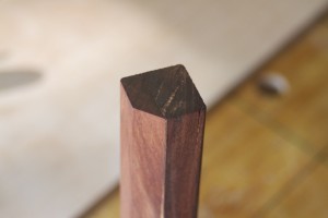
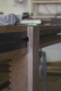
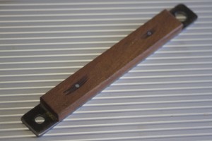
As if the above effort was not enough I decided that the edges of these dados are in need of a chamfer that would promote facile access for the piece of threaded rod intended to hook into these dados once our deadman enter into operational mode. For this purpose I used a V-groove router bit sized to allow me to chamfer both edges of each dado in a single cut. The modification of my guiding jig came in handy once again in lining up the cuts perfectly without much fuss. The results are apparent in the pictures below. Incidentally, you can also see the Ysterhout running down the middle of the deadman in the second picture.

IMG_5604IMG_5605

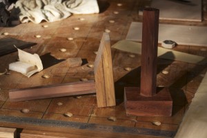
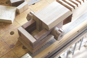
Now we move on to the construction of the moving parts of the deadman. First, we will look at the block of wood meant to support stock much like a peg on a regular deadman. This block of wood is meant to be height adjustable by means of hooking into the dados at the back of the main beam and (as always) another elaboration I simply could not resist.

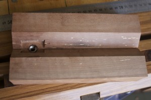
In the pictures below you will observe a collect of the petite pieces of wood chosen to make up the moving parts of the deadman. The second picture depicts the laminated blank earmarked to become the adjustable block. Please note that this block consisted of two equally sized parts clamped together in a face vice for the purpose of marking out the next cut. The cut was made on the table saw as illustrated in the next two pictures. It will become clear what I was aiming for as we progress.

IMG_5606IMG_5608IMG_5618IMG_5619

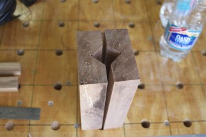
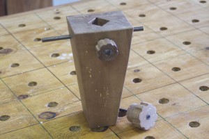
I drilled a 8.5 mm hole with the drill press in the valley of one of the v-grooves created by the previous cut. I then widened the hole from the v-groove side only deep enough to accept an insert nut for an 8 mm bolt. The insert nut was seated using the drill press and manpower. Next I chiseled out an area that would house the wooden brake. In the last two pictures you can see the wooden brake in it’s place.

IMG_5620IMG_5621IMG_5622IMG_5623IMG_5624

With the inside work done the block was glued together creating a diamond shaped channel (in actual fact it is square but positioned like a diamond) meant to accept an adjustable shaft. The orientation of the square channel was aimed at combatting the effects of wood movement, much like some of the better marking gauges. With this design the shaft will always sit tight when jammed into the 90° v-groove. If orientated differently it would rattle from side to side when the channel gets bigger and get stuck when the humidity swings the other way.

IMG_5630IMG_5629IMG_5661

The block was then shaped on the band saw to assume an elegant sloping appearance. The rough marks of the band saw were tidied up using a handplane. In pictures 3 and 4 you can see the threaded rod screwed and epoxied into place. These holes were drilled before the block was sloped in order to drill them parallel to the ends. I drilled 7.5 mm holes and screwed the 8 mm threaded rods in after lubricating it with epoxy. You can also see the knob turning the 8 mm threaded rod onto the wooden brake we seated earlier. I will write a brief post in the near future on how to make these knobs.

IMG_5698IMG_5699IMG_5845IMG_5846IMG_5847

In the next few pictures you can finally get an idea of how the support block function with the brake we made earlier. We already discussed the reasons behind the shape of the shaft, but here you can see want I meant. I slowly hand planed the shaft until it fitted perfectly. You will note the flat area on one of the corners of the diamond shape, which is where the brake asserts it pressure.

IMG_6997IMG_6998IMG_6999IMG_7000IMG_7001IMG_7004IMG_6996IMG_7002

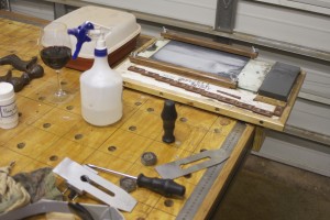
We will leave the the block’s evolution for the moment and shift our attention to the adjustable lower section meant to anchor the deadman to the floor. You can see how I used a Festool router to cut slots in a piece of Kershout. The choice of wood was driven by aesthetics. Kershout has a very deep colour once finished, which contrasts nicely with the light orange of the Assegaai. It also helps the deadman fit in with it’s brother the legvise. Yes I know, it sounds a wee bit girlish, but remember my goal is to bring into being workshop paraphernalia with a certain je ne sais quoi.

IMG_5658IMG_5659IMG_5665

The two bits of Kershout were separated and clamped in my face-vise. I then used this newly acquired gadget from Veritas to cut one single dovetail pin in each. The gadget is called a Veritas Dovetail Saw Guide System. You will find it in the Veritas catalogue downloadable from their website (find the link in the library page on this site) which makes superb reading for tool aficionados.

IMG_5837IMG_5839

In the pictures below you can see how I glued the Kershout parts into position after cutting the corresponding tails in a piece of Assegaai. I used the actual stoped dados in the bottom of the main beam, where the Kershout will slide up and down to keep the setup in the exact position while drying.

IMG_5840IMG_5841

In the next few pictures you can see how I made a quick test of how my design works. I clearly need to improve on my dovetail technique, but in my defense this was the first dovetail I did since a woodworking examination in 1987. I think it is pertinent to digress from my story-line at this point in time.

On that particular day I made two first class dovetails in the time the rest of the class were supposed to make one. My best mate Gerdie Smook used to share a workbench with me, as per usual I guess in most school woodworking classes around the world when it still existed. The problem was that Gerdie tends to be a danger to himself (and others in his immediate surroundings for that matter) in the shop environment. In this particular exam we were issued with a three dimensional drawing of a doveltail joint and given a bit of wood to whittle into something resembling the mentioned drawing.

The game plan was formulated several days in advance, as Gerdie were on the brink of failing woodwork as a subject and it would not go down well as son of the Headmaster. I made one copy of the joint in the speed of light and handed it over to Gerdie with the idea that he would not alter it at all, yet try to look busy sanding it lightly. I then grabbed his chunk of wood and and made his joint. Obviously being warm-up at this stage, his turned out better than mine. To add to the discrepancy, Gerdie managed to mutilate mine sufficiently (with the mentioned “light sanding activity”), to ensure that he got a much better mark than me. Despite that, I still regard what I did that day as the finest achievement of my non-existent woodworking career.

IMG_5842IMG_5844

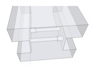
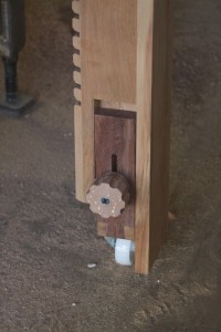
I made some of my usual crude Sketchup drawings to show what is happening in the engine room of this part of the design that is a bit difficult to see from the pictures above. As you can see I drilled two 7 mm holes lined up with the slots in the Kershout that slides up and down the stopped dados. Then I widened these holes on opposite ends to accept insert nuts for a 6 mm bolt. The bolt was sunk into a wooden knob and epoxied. The knob of each bolt obviously sits on the opposite end to the insert nut that it engages with.

Deadman 2Deadman

Here I added the caster meant to make it easy to slide the deadman along the side of the assembly table, hence “sliding” deadman.

IMG_5849IMG_5850

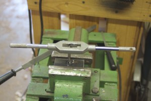
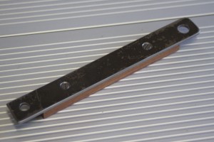
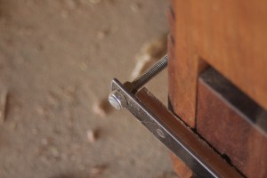
Since finishing the legvise (with a twist) I acquired thread cutting tools, which you can see in action below. I am in the process of cutting 8 mm thread in a piece of steel left over from another job, to act as the anchor in the T-channel on the side of the assembly table. You will remember how I had to weld bolts to a piece of steel to accomplish the same while creating the anchor for the legvise.

IMG_5851IMG_5852

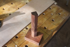
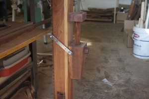
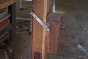
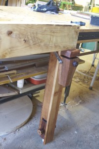
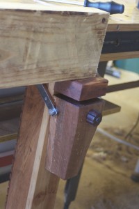
Finally you can get an idea of what we were aiming for with regards to this unique deadman. In the pictures below you can see the first “dry fit” to the assembly table. In the second picture you can see the two bits of scrap 6 mm plywood attached the inside of the face board were it nestles up against the side of the assembly table. These were added to bring the face of the deadman perfectly in line (flush) with the inside jaw of the legvise. In the third picture you can get an idea of how the height adjustable mechanism operate.

IMG_5853IMG_5855IMG_5854

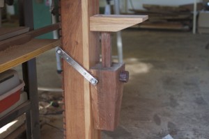
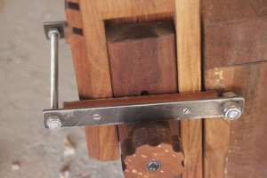
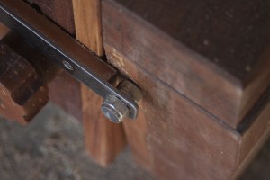
After all that fanfaronade, let’s get back to the adjustable support block. I made the arms in the pictures below to wrap around the main beam of the deadman while being attached to the support block and the 6 mm threaded rod that hooks into the profusion of dados at the back of it. The wood is meant to created a soft wood-on-wood feel when adjusting the support block, but also considers the matter of wear.

IMG_5858IMG_5859IMG_5860

In then next few pictures you can see how the support block works. It hooks into the appropriate dado depending on the hight needed for the job and has the ability to make fine adjustments with the “marking gauge mechanism” for lack of a better term. You will note the use of two lock nuts on either side of each steel/wood-arm, allowing precise adjustment for a custom fit.

IMG_6996IMG_6991IMG_6992IMG_6993IMG_6994IMG_6995

Every deadman deserves a good manicure before being flung into another samsara. In this case a facial treatment with Tung oil diluted vigorously with mineral turpentine. After only one layer of this I rubbed some (you’ve guessed it) Ballistol on for good measure.

IMG_5861IMG_5862

In these pictures you can see how the deadman and the legivise function together for the first time.  At the time I was working on t-brackets to hang from the rafters in order to keep a few boards out of the way while it acclimatizes to the shop.

IMG_5867IMG_5868

IMG_5869IMG_5870

Sandpaper storage

This past weekend I finally got round to building a small cabinet to house my sandpaper in an orderly fashion. I used scrap “shutterboard”, which is some really nasty stuff they sell in this part of the world as so called “plywood”. It is more fond of warping than a pig’s tail. To stabilise the shutterboard sides I used Supawood (MDF) for the back, some scrap chipboard for the base and top, and 3 mm hardboard (Masonite) for the dividers.

In the pictures below you can see how I used my Festool QF1400 router with a 3 mm straight bit to cut the dados. Please note the jig resembling a woodworking square used to guide the router. These are very easy to build as you can see. I might do a quick post on how to build them in the near future. You can also see how my assembly table is assisting in holding the work pieces. You can see the F-style clamps and benchdogs both utilising conveniently located dogholes. If you are interested to see how I built this assembly table, find the posts under the category “Bench”.

IMG_6910IMG_6911IMG_6912

Here you can see how I used the F-style clamps to fix one of the sides of the cabinet to the side of the table. The f-style clamps slide into the T-channel on the side of the table. I elevated the setup by using my Lie-Nielsen no. 4½ Smoother on it’s side. This is a very useful trick in lots of different situations. In this case I elevated the setup in order to get two scrap pieces of hardboard (Masonite) into the dados (as shown in the next set of pictures) to line the side and back up perfectly before screwing it together.

IMG_6913IMG_6914

You can see the scrap piece of hardboard in the first picture and how it helped lining up the dados perfectly in the next picture.

IMG_6915IMG_6916

Sliding the dividers in is easy if the dados are well lined up.

IMG_6917IMG_6918

Next I glued some Ysterhout edging to hide the chipboard, plywood and dados. This is a point were I disagree with most of the authorities who suggest that one should chuck away every bit of scrap wood left over from previous projects. Maybe it is a cultural thing, being born and raised in Africa, but chucking good wood away is absolutely against my grain (if you excuse the pun). Most of the projects I have written about so far on this blogsite were done utilising cutoffs, including every single part of this sandpaper storage cabinet. The chipboard that was used for the top and bottom of the cabinet were recycled from the crates my father build to transport his woodworking tools over a distance of 1800 km to my current shop. Before that it did duty in umpteen other cameos.

IMG_6919

Here you can see the cabinet in it’s final resting place. It sits under the so called “effulgent arm” in order for the mentioned lighting impedimenta to swing past it when necessary. I will write a post on the lighting arm in the near future. If you enlarge the last photo you can see how I indicated on the right hand side which grid of sandpaper goes where. On the top shelve (no unfortunately no booze) I keep the roles of 3M Adhesive-backed Sandpaper.

IMG_6926IMG_6925

Legvise with a twist (Chapter three)

In the final chapter of this series of posts we will look at how I finished this unique legvise. It could be a useful idea to other woodworkers who does not have a proper dedicated workbench.

In these first pictures you can see how I made the rollers for the parallel guide. Unfortunately I only saw the idea to use skateboard wheels after I built these, but I would recommend using them if you still have to build yours. I used an inexpensive plastic wheel used to guide automatic steel gates, which is very common in this part of the world where we all hide behind electric fences. It works fine but does not have a smooth low friction ball-bearing system like the skateboard wheels.

100_1092100_1093100_1094100_1095100_1096

Next I used my newly purchased Festool router to cut a dado that would accept the Kershout strips meant to clamp the edges of the leather that would ultimately grace the faces of the jaws.

100_1101100_1102100_1103100_1107

I then assembled the legvise temporarily in order to drill the hole for the large single screw vise.

100_1109100_1110100_1111

Due to the length of the “nut” (pictured below) that accepts the screw, I had to add some wood to the inside jaws, as seen in the pictures above.

100_0372

Below you can see how I used handtools to custom fit the “nut” into the inside jaw for a lifetime of abuse.

100_1112100_1113100_1114100_1115

I then fitted the screw to the chop.

100_1120100_1121

Below you can see how I glued leather from a Red Dear I shot while living in New Zealand to the inside of both jaws.

100_1122100_1123100_1124100_1125

The leather was then clamped into place tidily using custom sized (by using handplanes) Kershout strips screwed into a shallow dado on the sides of the jaws.

100_1126100_1132100_1135100_1136100_1137100_1138100_1141

Next I had to shape a scrap piece of steel that could slide into the T-channel on the side of my assembly table in order to fix the inside jaw to the table in a manner that would make it easy to move the legvise from one location to the next if needed. You can see how I welded nuts to the steel as at this point in time I still did not have thread cutting tools. You will also notice that the piece of steel was deliberately bent slightly so that once the bolts are tightened it would apply even pressure across the length of it.

100_1147100_1148

From this point on you should be able to see what I was aiming for. In the first picture you can see how the rollers and adjustable feet were attached. The next pictures show how the two jaws were assembled by means of the vise screw for the first time.

100_1160100_1161100_1163100_1165

The first time I attached the legvise to the assembly table to test out a few things. I realised that I had to do a few adjustments to the feet.

100_1167

Here I am shaping a piece of Witpeer in order to turn the ends of the handle.

100_1193100_1194100_1195100_1196100_1197100_1199100_1200

Here you can see how I modified the feet. I inserted two pins that was epoxied into place that would ultimately sit inside a small rubber disc. The area between the disc and the nut received a coat of grease to allow the adjustable feet to rotate easily while being firmly pressed against the floor.

100_1208

I am not sure what the correct term is for this instrument, but it is the one that gets jammed into the wholes in the parallel guide and you can see that I made mine from scratch.

100_1209

Finally the legvise was fitted to the table in the position I thought would be best for now. In the second picture you can see what I was on about regarding the modification of the adjustable feet. You will also note the nuts that was added to lock the threaded rod feet into place once it is adjusted to the correct height. The third picture show the nameless instrument in position in the parallel guide.

100_1216100_1218100_1222

The final product was well worth the effort displaying the beautiful orange and grayish-yellow colours of the Assegaai and Witpeer. I have to say that it works even better than anticipated and I would not change too much at all if I build another one.

IMG_5567IMG_5568


You can start looking out for some posts on the sliding deadman that I built to toil in tandem with this baby.

Old Stanley Bailey handplane rehabilitation

My father gave me most of his tools some years ago when he decided to downscale and pursue other interests. He was very much a powertool woodworker as apposed to a hybrid woodworker (someone who uses both hand tools and power tools) or a handtool woodworker. I never even knew that he was as his way was the only way I knew, until I started reading American woodworking magazines and listening to podcasts such as the one by the Modern Woodworkers Association (my favourite) and Wood Talk (highly recommended). Now I realise that there are other ways to approach woodworking conundrums.

It is not as if I am not grateful for everything I learnt from my Dad, as it certainly got me hooked to woodworking in a big way, but I am finding myself gravitating towards quality handtools with a vengeance. I guess that would make me a hybrid woodworker with fairly basic handtool skills at present.

This is really a roundabout way to get onto the primary purpose of this post, which is the rehabilitation of the two old Bailey handplanes my Dad handed down to me. It is a no. 4 Smoothing Plane and no.5 Jack Plane that really needed serious attention. I never even knew that one should sharpen the plane irons as my father and I never did. Probably, in hind sight, because we never used them. For this reason they never seem to work very well, which did not encourage any further scrutiny.

That was until I watched the DVD on Plane Sharpening by David Charlesworth and using a sharp Lie-Nielsen No.4½ Smoother. It would not be too much of an exaggeration to say that it was an epiphany. A sharp handplane is poetry in motion. It is psychotherapy for a shrink … literally in my case. David also explains very clearly in his DVD what comprises a functional and well tuned (apart from a sharp iron) handplane, which is all very useful to any woodworker, but especially to plane rehabilitators.

Armed with this new knowledge I set about to rehabilitate these family heirlooms. In the first few pictures you can get an idea of the state they were in. It used to be toilsome to slice Parmesan cheese with these planes, to be honest.

100_1202100_1203100_1204IMG_6814

First step was to flatten the soles of these planes and it turned out that they were in some serious need of this particular ministration. An added bonus of doing this is that it makes the shiny parts of the plane body smile with a rewarding gleam. I have to warn you that this is hard work that can take time and perseverance from a woodworker. You do not have to get it 100%, but the toe, the area behind the mouth and a reasonably large area towards or at the heel all needs to be in the same plane.

A Magic Marker is very useful to demonstrate the areas that needs attention. Drawing a grid (as shown) before taking a few swipes over wet-and-dry-sandpaper fixed to 10 mm thick float glass, would reveal the troublesome spots in no time. Please note that I left the plane irons clamped in their usual position, only making sure that they are retracted well into the plane body in order not to get damaged by the flattening activity. The reason behind this is that the clamping action of the lever cap deforms the sole ever so slightly which means that you want to flatten it while under tension.

IMG_6812IMG_6813

The remnants of gridlines clearly indicate the low lying areas as seen below.

IMG_6815IMG_6816IMG_6817

Then it becomes a question of elbow grease, burning some midnight oil or whatever it might be called. Here you can see how I used my sharpening jig to do the flattening. If you want to read the post on how I made this jig find the post called “My version of Deneb’s sharpening jig” under the category “Jigs”. This jig clamps wet-and-dry sandpaper on a piece of float glass by means of two cauls.

IMG_6818IMG_6819IMG_6820IMG_6821IMG_6822

The final product is well worth the effort I thought.

IMG_6823

Next I took the planes apart completely, including removing the plane irons with their chipbreakers, the frogs, the totes and knobs.

IMG_6824IMG_6825IMG_6826IMG_6827IMG_6829

Here you can see how I sharpened the new replacement blades I bought from Lie-Nielsen. If you are interested in purchasing replacement blades for old Stanleys, check out Lie-Nielsen’s website, they have the whole range. Their blades are definitely the business. Their blades are prepared at a primary bevel angle of 25º and ground flat as … oh no just remembered this is a family website … but you really do not have to do too much work on the back at all.

I honed a 33° honing angle on my 1000 grid Ohishi waterstone and polished a 35º final cutting angle on a 10 000 grid Ohishi stone. Both blades were sharpened with a cambered edge.

Blade bevels.Blade bevels 2.IMG_6830IMG_6831IMG_6832IMG_6869IMG_6870

In the picture below you can see the Nagura stone I use with the 10 000 grid stone.

IMG_6835

Here you can see how the totes and knobs looked like prior to rehabilitation. Clearly some type of varnish left that was starting to look seriously weathered. I removed the the varnish with a card scraper before tidying it up with sandpaper.

IMG_6836IMG_6837IMG_6838IMG_6840

A last picture before the frogs came off.

IMG_6841

The two screws that fix the frog to the body of the plane is evident in the first picture. In the third picture you can see the screw that helps you position the frog during reassembly depending on how tight you want the throat.

IMG_6842IMG_6843IMG_6845

Next step was to carefully remove the worst of the rust from the frog’s surface that supports the blade with a fine flat file.

IMG_6846IMG_6848IMG_6849IMG_6850

In the first picture below you can see how I then used a magic marker to blacken all the surfaces that is in contact with the back of the blade. In the next picture you can see the setup I used with 150 grid wet-and-dry sandpaper on a piece of float glass on the edge of the table in order to easily hone the most important front section of the frog. In the third picture you can see how the leftover magic marker indicates the areas that needs more attention after just a few strokes on the sandpaper. The last picture show how it is all cleaned up and flat as … yes you know what I mean.

IMG_6851IMG_6852IMG_6853IMG_6855

Here you can see how I cleaned up and flattened the areas of the frog that is in contact with the plane body.

IMG_6856

Speaking of plane bodies, here you can see how they look prior to a Ballistol treatment.

IMG_6857

One of the most important parts of this rehabilitation operation is the work done on the chipbreakers. You want to flatten the area in contact with the blade at an angle that will ensure that the absolute tip of the chipbreaker sits flat on the back of the blade. This is accomplished by the setup as shown. You can see how the angle created will ensure that only the tip ends up flat on the blade.

IMG_6861IMG_6858IMG_6859

Here you can see how I decreased the angle slightly for honing and polishing. In the last picture you might be able to appreciate the perfectly polished and flat area that will ultimately sit on the back of the blade.

IMG_6863IMG_6864IMG_6862

The lever cap being made of cast iron is much easier to flatten, but again remember to set it up so that you only flatten the area that matters at the very tip that will be in contact with the chipbreaker. These lever caps were not even close to flat in the mentioned area.

IMG_6865IMG_6866

Here you can see the totes and knobs before and after a Ballistol treatment.

IMG_6867

Both totes were very wobbly due to very slack tolerance around the two raised cast iron areas on the base. I decided to remedy this by inserting some Epoxy putty and squeeze the tote into position, in order to create a perfect fit.

IMG_6871IMG_6872IMG_6873IMG_6874IMG_6875IMG_6877

Finally all the parts were reassembled with the frogs set up to create a very tight throat on both planes. I can really recommend doing this for those of you who do not mind some elbow grease in return for a pleasing precision tool. There can be no comparison between how these planes cut post rehabilitation compared with prior to it. It is an absolute pleasure.

IMG_6878IMG_6879IMG_6880IMG_6881IMG_6882IMG_6883


As per usual, the proof is in the pudding. Here are some of the first shavings I took. It is poetry, I tell you!

IMG_7096

I think they are ready for another few hundred years of work.

22/4/2014

IMG_0187IMG_0188IMG_0191IMG_0192IMG_0193