Flesh and blood in the shop

I thought it would be a good idea to start collecting photos of the various family and friends who spends time with me in the workshop over the years. Seeing that the workshop is my haven where I spend most of my leisure time, I like sharing it with the family every so often. I enjoy getting the younger generation interested in the challenges and adventures of the creative process, so most of what you will see are the kids being introduced to the shop.

Another aspect that seems important to me is to get the (let’s call them) experienced bunch in the shop to get the flow of knowledge from one generation to the next going. Here I am for example working with my father-in-law.

100_0315100_0316

My mother likes to hang around chatting about all kinds of stuff while I toil away at some project.

100_0395

My daughter sometimes use my assembly table to practice for one day at Uni when she might feel the need to dance on the bar or tables, hopefully completely dressed throughout. Her mother seems to encourage this particular activity.

100_0356100_0357100_0358

My son Didi and his mate Connor are serial knife smiths. They convert every freaking stick they pick up into a knife. Here you can see him sharpening another deadly wooden dagger.

100_1155


Sometimes he likes posing with new jigs …

IMG_5569

… and other times working half naked, although I have to say in his defense that it gets seriously hot around these parts. In the pictures below he is working on a bird feeder.

IMG_5570IMG_5572IMG_5575IMG_5576IMG_5577IMG_5578IMG_5579IMG_5580IMG_5581IMG_5582IMG_5583IMG_5593IMG_5596


The wife on the other hand usually keeps her clothes on, but tends join me for a chat while she savors a glass of wine.

IMG_6241IMG_6242

Aoife has helped me to plane a few boards.

IMG_5651IMG_5653

I try to get them used to good habits such as wearing eye and hearing protection.

IMG_5864IMG_5865

Here is Didi with his mate Connor helping me to rip Assegaai on the table saw. Connor is such a workshop junky that he sometimes hangs out with me in the shop while Didi is not even around.

IMG_7109IMG_7104

I found that they can be very handy in cleaning rough boards before we feed it to the planer.

IMG_7111IMG_7112IMG_7117

Apprentice cabinetmaker Connor during one of his solo sessions in the shop.

IMG_7286

I have now started giving them small projects to keep them busy in order to get to know various basic tools and material.

IMG_7306IMG_7307IMG_7308IMG_7309IMG_7310

The whole family sunbathing in front of the shop 3/8/2013.

IMG_7523IMG_7524

The wife in action cutting out letters to put Aoife’s name on her (my daughter) bedroom door. 3/8/2013.

IMG_7533IMG_7534IMG_7535IMG_7538IMG_7539IMG_7540IMG_7542

19/8/2013 – I took these photos on the weekend. Granddad Derick supervising proceedings at the drill press during their recent visit to the Land of the Brave.

IMG_7615IMG_7616IMG_7617IMG_7618


1/9/2013 – The wife and kids left me all alone for the latter part of last week as they took advantage of the school holidays and joined our good friends (one of which you have already met earlier in this post by the name of Connor). They all had a ball of a time at the legendary Henties Baai, while I continued to save lives here in Windhoek. While they were away, our family lap-dog became my woodworking buddy. Her name is Pipsqueak and she is an imposing Miniature Pincher. We supported each other through the tough times, as you can see.

IMG_7868


25-26/1/2014 – Didi and Connor working on an axe handle ….

IMG_9532IMG_9534IMG_9536IMG_9537IMG_9538IMG_9540IMG_9541IMG_9542


… which Didi finished today.

IMG_9584


10/3/2014

The hooligans helping to clean up shavings from the planer and used it as mulch for the trees outside the shop.

IMG_9946IMG_9947IMG_9948IMG_9949


3/11/2014

My cousin Jogy creating a couple of orifices in my bench top to accommodated planing stops. He is particularly skilled at this type of activity being a Urologist by training.

IMG_2287IMG_2288


IMG_2350IMG_2366IMG_2367


IMG_2368IMG_2369IMG_2370IMG_2371IMG_2372IMG_2373


IMG_0180IMG_0181IMG_0182photo 1


IMG_2385IMG_2386


IMG_2389


IMG_2532IMG_2533IMG_2567IMG_2569IMG_2570IMG_2571IMG_2572IMG_2573IMG_2577IMG_2578


IMG_2612IMG_2613

Glue roller

A problem I have encountered as a result of the very dry climate (ambient humidity 30-35% in my shop during winter months) and frequently needing to laminate heaps of small pieces of wood together has been the short open-time of the PVA glue I use. The reason why I need to laminate is the nature of the hardwood boards I have. There are very few of these boards that one can use as is. For most of them I need to cut a whole heap of smaller pieces to make up bigger ones by lamination. If you have a look at the post I wrote on my “Legvise with a twist” you can get a better idea of what I mean.

The problem then becomes one of trying to apply adequate amounts of PVA to all these surfaces and clamp before the glue dries. The first improvement  to my technique was to use a paintbrush to apply the PVA, rather than the off-cut (shaped like a spatula) of wood I used to use. Then I saw someone using a roller and it seemed so much more efficient. Problem was that the only ones I could find to buy was the ones supposed to be used for paint. They are soft and would absorb more glue than apply.

As per usual I then decided to modify an old paint roller to serve my specific needs to a tee. I turned the cylinder in the pictures below out of witpeer wood. In order to create an area that would be very resitant against wear I epoxied a penny-washer to both ends of the cylinder, as you can see below.

IMG_7086IMG_7087IMG_7085IMG_7090

Once that was set I tested the cylinder on an old paint roller handle. It seemed to work well.

IMG_7082IMG_7083IMG_7084

I then treated the wooden cylinder with more than ten coats of floor varnish thinned with mineral turpentine. This was an attempt to keep the worse of the moisture on the surface rather than in the wood, as using and cleaning a tool like this will inevitably expose it to lots of H2O.

IMG_7123IMG_7124IMG_7121IMG_7122

The final product has sped up my glue application with a vengeance.

IMG_7470


In action on a plane to be.

IMG_6937IMG_6938

11/11/2013 – Over the past week or so I improved the glue roller by removing the horrible plastic handle and replacing it with a shop turned witpeer one. If you are interested, I wrote an entire post on how I made these handles (mainly as file handles) under the hand tool category. The only way I could get rid of the plastic handle was to cut it away using my bandsaw. I then cut thread into the stainless steel rod that was left and screwed it into the handle with epoxy acting as cutting fluid.

IMG_8524

Here you can see how I applied a thick layer of epoxy to prevent any moisture from getting to the end grain.

IMG_8523

In order to hang the roller I lined a hole with this thin piece of copper pipe. After the epoxy dried I tidied up the protruding pipe and Bob’s your Uncle.

IMG_8528IMG_8527

IMG_8529

IMG_8561


Shop made Idiosyncratic Wooden Scrub Plane

June/July 2013

The second plane I decided to build was a scrub plane. Actually I built it alongside the Petite Wooden Smoother as described in exhaustive detail in the post with the same name, but finished off it’s wee cousin first and then moved back to the pugnacious old-timer.

This was the only piece of beech I could find at the time.

IMG_6908IMG_6907IMG_6906

I decided to use ysterhout for the sole of this plane. In future I plan to try to cut these 8 mm “veneer” on my band saw, but in this particular case I had to plane it down with the thicknesser and lost heaps of wood, electricity and time in the process. Since this wasteful experience I have managed to rehabilitate the mentioned bandsaw, so my wish should be possible in future. You can see how I am cutting the actual sole from the strip of ysterhout.

IMG_6932IMG_6933

In the first picture you can see both of the initial planes prior to lamination. In the second picture you can appreciate the grain orientation of the scrub plane.

IMG_6934IMG_6936

I did not take any pictures of the lamination process of the scrub plane but it looked similar to how I did the smoother in the picture below.

IMG_6937


The clamps exerted some serious pressure, which is what one wants in this particular instance.

IMG_6941IMG_6942

Then I used a handplane to square up the sides relative to the sole.

IMG_7005IMG_7006


In the next picture you can appreciate the grain orientation. In the second picture the square that guides this process is evident.

IMG_7007IMG_7008IMG_7009


Here you can see the beautiful shavings taken by my rehabilitated Stanley Jack Plane.

IMG_7010IMG_7012


My newly rehabilitated Bandsaw did a stirling job of cutting the sides off this plane blank. Please note that I deliberately chose to have the ysterhout at the top to prevent blow-out.

IMG_7023IMG_7024IMG_7025IMG_7026


The result an absolute joy.

IMG_7027IMG_7028IMG_7030


I then removed the saw marks with a hand plane.

IMG_7137IMG_7138


In order to reduce the centre section to the correct width I used the thicknesser. I aimed for 3 mm wider than the blade. This blade is a replacement blade for the Lie-Nielsen scrub plane at 1½” wide with a 3″ radius to take a mega chunk of timber with every pass.

IMG_7139IMG_7140IMG_7141


Below You can see how I glued another piece on to the centre section in order to produce the handle. I decided to used my own adaptation of a saw handle for this plane.

IMG_7164IMG_7165IMG_7166


I used one of the saw handle templates from the TGIAG (Two guys in a garage) website as a starting point to shape the handle of this plane. I can really recommend this website if you are looking for a saw handle templates. They have heaps which are downloadable for free in pdf format. I decided to tweak the S Biggins backsaw handle into a scrub plane handle. In the pictures below you can follow the process.

IMG_7358IMG_7359IMG_7360IMG_7361IMG_7362IMG_7363IMG_7364IMG_7365


I then traced the outlines on to the plane blank and elaborated a few extra curves to get it to the top of the ramp. Next step was to take to it with the drill press after marking out the exact location and size of the holes that would form the curves that are too tight to navigate with the bandsaw.

IMG_7367IMG_7366IMG_7373IMG_7375


The central hole was removed with a jigsaw …

IMG_7378IMG_7380IMG_7379


… and the rest with the bandsaw. At this stage I took quite a bit of time to come up with a idea and method to shape the sides to fit in with the handle design.

IMG_7383IMG_7384IMG_7385IMG_7387IMG_7388


In the end I came up with this idea. I traced the outlines of the centre piece on to one of the sides, drew a type of halo following the handle lines in some parts and taking it’s own route in others. I removed the waste with the bandsaw and then used it as a template to trace it onto the other side.

IMG_7389IMG_7390IMG_7391


In the pictures below you can get an initial idea of what I was aiming for.

IMG_7392IMG_7393IMG_7394


The arduous task of rounding and smoothing out the rough sawn curves were completed using hand tools predominantly.

IMG_7395IMG_7396IMG_7397IMG_7398IMG_7399


I marked out guiding lines with a pencil using my fingers as a fence. The idea was to cut these before glueing the plane together as it would be difficult to access the area next to the handle once glued. I used a small Lie-Nielsen block plane to cut the chamfers.

IMG_7400IMG_7401IMG_7403IMG_7404IMG_7405


The rest of the curves were smoothed out with a variety of files.

IMG_7408IMG_7409


Once all of this was done I used my Bandsaw Mitre-sled to cut the ramp. You can find an entire post on how I have built the sled on this website.

IMG_7410IMG_7411IMG_7412


The curve cut into the toe section was designed that way to allow more space for the accumulation of heavy shavings as this is a scrub plane that does not require a tight mouth.

IMG_7413IMG_7414IMG_7415IMG_7416IMG_7417IMG_7418


I used the off-cut wedge to support the ysterhout fibers of the ramp in order to prevent blowout, as you can see below. I then planed it flat and square with a freshly sharpened Lie-Nielsen no. 4½ Smoother. The result is clear from the pictures.

IMG_7420IMG_7421IMG_7422IMG_7423IMG_7424


To ensure it is absolutely perfect I used the setup with two different grids of 3M adhesive-backed sandpaper on float glass. It is worth while to take a bit of time to get this surface perfect as it is the most important part of the whole project in terms of the functionality of the plane. If it is off by a few thousands of an inch, the blade is likely to chatter with a vengeance.

IMG_7425IMG_7426IMG_7427IMG_7428IMG_7429


In these pictures you can see the setup I use to mark out the positions of the toe and heel sections relative to each other and the sides. As this is a scrub plane that will eventually have a fairly wide throat. I positioned the heel section, marked it’s position, clamped it in place, got the blade in position, slid it down all the way to the guide, slid the toe section to gently touch it and marked it in that position. The throat will be opened up further at a later stage.

IMG_7430IMG_7431IMG_7432IMG_7433IMG_7434


As I explained in my post on the Petite Wooden Smoothing Plane, I use dimensions/measurements from an article entitled “Wood planes made easy” by David Finck in Fine Woodworking Magazine to mark out the location of the cross-pin. Once you have drilled one, you can get the other into the exact place by clamping the plane together and using the first hole as a guide to drill the second on a drill press. Also note the small panel pins I use to ensure that I can fit the plane back to exactly the same alignment after drilling the second cross-pin hole and the compulsory dry fit.

IMG_7435IMG_7436IMG_7438IMG_7439IMG_7437IMG_7441IMG_7441


From this scrub plane I used my Lie-Nielsen carcass saw to cut the cross-pin made of Assegaai for it’s renowned elasticity, flexibility and stability. I rounded the ends with a file.

IMG_7443IMG_7444IMG_7445


The compulsory dry fit.

IMG_7446IMG_7447IMG_7451IMG_7450IMG_7449IMG_7448IMG_7452IMG_7453


The glue-up.

IMG_7454IMG_7455IMG_7456IMG_7457IMG_7461IMG_7462IMG_7463IMG_7464


Fresh out of the clamps, with quite a bit of finishing left to do.

IMG_7471IMG_7472IMG_7473


I used my Lie-Nielsen no. 4½ Smoother (not pictured) to flatten the sole initially. The final flattening would take place once the cap iron/chip-breaker combination is made and holding the blade tight against the ramp.

IMG_7474


I found this piece of scrap angle iron with which I planed to make the cap iron/chip breaker combination. The stainless steel thumb screw was also a discovery amongst all my carefully hoarded jewels (which is frequently being referred to as junk by others).

IMG_7501IMG_7502


To start with I epoxied a short piece of stainless steel threaded rod to the thumbscrew, because I do not know how to weld stainless steel.

IMG_7517


I then attacked the steel with my grinder.

IMG_7518IMG_7519IMG_7520


It took more than an hour of elbow grease to cut the 45° bevel using the grinder and various grids of wet-and-dry sandpaper on glass together with a honing guide.

IMG_7521IMG_7522IMG_7525


The slight indentation you see is where the cross-pin would get into contact with the iron cap. In the pictures below you can see the hole for the thumbscrew being drilled and tapped.

IMG_7526IMG_7527IMG_7528IMG_7529IMG_7530IMG_7531


The final touches were done on a 1000 grid Ohishi waterstone using the so called “ruler trick” made famous by David Charlesworth. This is to ensure that the back of the cap iron/chip breaker combination sits absolutely flat on the blade.

IMG_7532


As this is a scrub plane I opened up the throat/mouth generously.

IMG_7536IMG_7537


In these pictures you can see how once again I drew the guiding lines for shaping the nose of the plane on the sole to prevent blowout of the ysterhout fibers when chewing the waste away with the bandsaw.

IMG_7543IMG_7544


Prior to cutting away the above curve I drilled out an area as shown using a Forstner bit. This is a unique (as far as I am aware as I have not see any other planes looking like this during my extensive internet research) design feature aimed at getting the best of both worlds in terms of having the big flat area at the front of the plane to press down and hold, yet have a nice grip to lift the plane during the back stroke. I find that with a longer and therefore heavier plane like this it is definitely a bonus to be able to curl your fingers into the nicely rounded slot. An added benefit as you will see later is that it adds some je ne sais quoi to the appearance of the plane.

IMG_7545IMG_7546IMG_7547IMG_7548IMG_7549

Here you can see what I was aiming for.

IMG_7550IMG_7551

I then extended the chamfer of the top edge of the sides to joint up round the actual nose of the plane using a file.

IMG_7552IMG_7553

After some TLC it is starting to look quite sexy.

IMG_7556IMG_7557

Here are heaps of photos from umpteen different angles with the cap iron/chip breaker and thumb screw in place.

IMG_7559IMG_7560IMG_7561IMG_7558IMG_7581IMG_7582IMG_7583IMG_7586IMG_7587


Finally, (just to show off) a few photos posing on a beautiful Rhodesian Teak log.

IMG_7603IMG_7605IMG_7600


4/9/2013 – In the picture below you can see it with it’s Fore Plane cousin at the Finishing Spa.

IMG_7930


Another step closer to finished. Now it only needs a coat of liquid wax tomorrow night.


IMG_7928


14/7/2014

I finally got round to cover the steel parts (lever and lever screw) with wood. I used a small piece of Kaapse Swarthout that fell off when I turned something else for the lever screw and Tamboti for the lever. Both bits of wood were epoxied to the steel.

IMG_1664IMG_1666IMG_1667

I really think it adds some je ne sais quoi to my favourite shop made plane’s appearance.

IMG_1713IMG_1714IMG_1715IMG_1716IMG_1717IMG_1718

Petite Wooden Smoothing Plane


I have been reading about and planing to make my own wooden planes for about a year now. I first thought of the idea when I realised how expensive it is to order good quality planes from the USA. For every two Lie-Nielsen planes I pay for an extra one in shipment fees. Make no mistake, the people at Lie-Nielsen have the best customer service I have ever come across and as everyone knows their planes are superb. Yet, sending it half way around the globe costs money.

The more I read about the wooden versions, the more it sounded like they might almost be better than their heftier cousins. Being a bit of a traditionalist, the idea of building my own wooden planes started to gain some momentum. I then had discussions with Deneb Puchalski of Lie-Nielsen around which blades might be best for the types of planes I wanted to build. He was very helpful and in the end I decided on:

1) Three x 2″ wide standard blades with chipbreakers (25 degree primary bevel)


2) One 1¾” wide standard blade with chipbreakers (25 degree primary bevel)


3) One Scrub plane replacement blade 1½” x 3/16 (thick)


4) One large shoulder plane replacement blade 1¼” x 8¼” x 0.140″ (thick)
The blades arrived on the 11th of June 2013 at which time I started to hunt down beech. Surprisingly, I found some in the Land of the Brave. I decided to first build a smoother and a scrub plane to warmup.
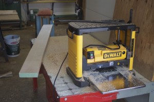
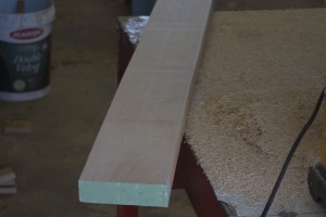
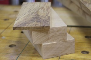
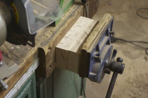
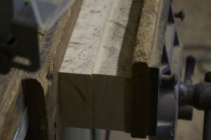
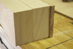
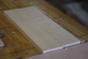
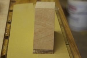
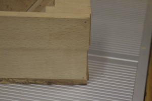
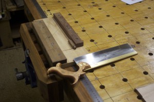
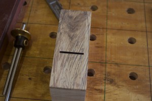
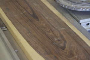
In the pictures below you can see the first chunk of beech after it received attention from the planer.

IMG_6906IMG_6907

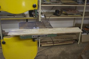
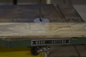
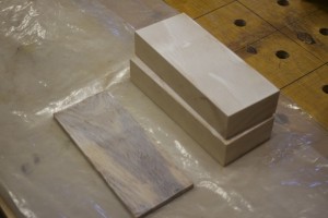
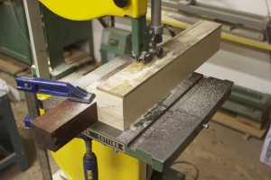
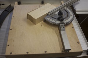
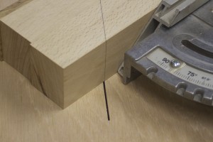
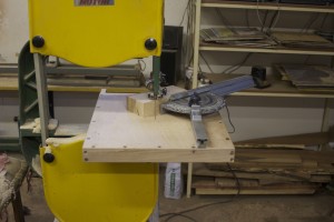
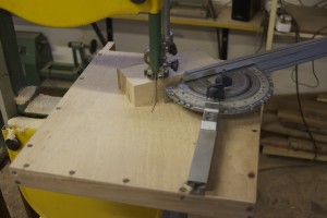
At this point in time I still did not rehabilitate my bandsaw (thus not able to re-saw at all and definitely not ysterhout in any dimension approaching what was needed), so I had to plane a fairly small piece of ysterhout down to about 8 mm thickness (from about 24 mm). I wanted to use this incredibly hard wood for the soles of my planes. In the pictures below you can see how I used the bandsaw to cut the sole of the smoother.

IMG_6932IMG_6933

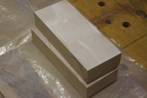
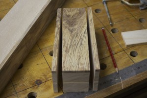
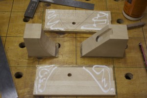
After studying the grain of the beech I decided to laminate it as you can see in the pictures below. It is impossible to find beech in bigger dimensions (around these parts) so lamination was my only option. Speeaking of which, I can really recommend the documents on building wooden planes written by Larry Williams and his partner at Old Street Tools. You will find the link on the library page of this site. There are articles on grain orientation, best woods to use etc etc.

IMG_6935

Here you can see how I laminated the parts.

IMG_6937IMG_6938IMG_6939IMG_6940

For some or other reason I decided to stick it in the face vise, which is not the best as the two jaws are not completely parallel, and I have made this mistake before. Anyway, it came out OK, but I really need to stop doing this.

IMG_6943IMG_6944

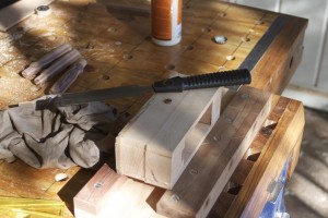
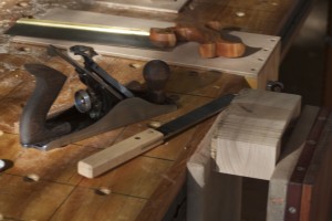
Next step was to hand plane the sides dead flat and square to the sole. You can appreciate the beautiful soft shavings generated by my newly rehabilitated Stanley no.5 Jack Plane. I wrote a complete post on this project which you can find in the category by the name of “Rehabilitation of old tools”.

IMG_7010IMG_7007IMG_7012

In order to make the next cut I was forced to spend most of the next week trying to fix and tuneup my old crappy bandsaw. The results however made it well worth my while. After the tune-up it sliced such perfect strips off the side that it only took a few strokes with the plane to get them as smooth as a baby’s bottom …

IMG_7031IMG_7024IMG_7032

… as you can see here.

IMG_7133IMG_7134IMG_7135IMG_7136

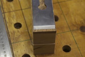
I then used the planer/thicknesser to get the inside close to the correct width. Maybe a bit less than 3 mm wider than the width of the blade. For this Petite Smoother I chose the 1¾” blade.

IMG_7142


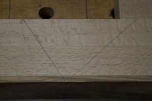
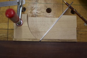
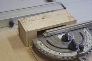
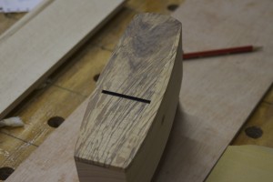
Here you can see how I marked out the bedding angle at 51º (just to be different of course).

IMG_7144IMG_7145

In order to make this next cut I had to build a jig for my bandsaw. I call it a “Bandsaw Mitre-sled”. You can find and read an entire post on this project under the above name …

IMG_7146IMG_7147IMG_7148IMG_7149

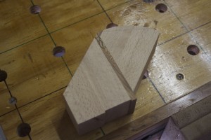
… here you can see the actual cut.

IMG_7150IMG_7151IMG_7152IMG_7153

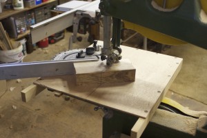
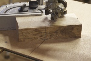
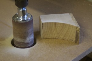
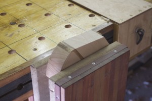
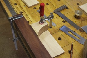
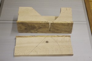
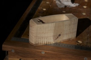
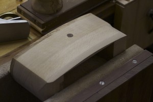
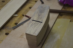
In the first picture you can see the toe and heel section after the first cut. In the next pictures you can appreciate the curve that was cut in the toe section.

IMG_7154IMG_7156IMG_7157

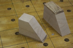
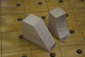
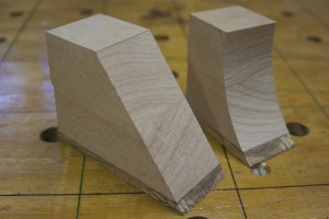
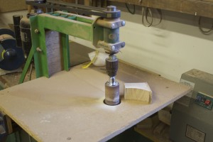
I used the Green Monster to smooth the curved surface of the toe section.

IMG_7158IMG_7159

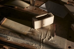
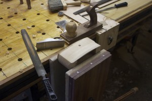
In order to prevent blowout of the Ysterhout sole while planing the so called ramp, I used the wedge (off-cut) that was created by the two cuts made earlier. You can see how I clamped it in the legvise to support the fibers on the delicate edge of the sole.

IMG_7167IMG_7168IMG_7169IMG_7170IMG_7169IMG_7171


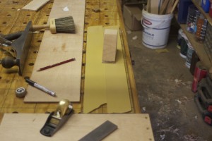
After getting rid of the saw marks left by the bandsaw by means of the old Stanley Jack Plane I used the 3M Adhesive-backed sandpaper on a sheet of float glass to get it 100% flat. You will note the technique I use frequently in scribbling on the area with a 2B pencil before sanding to identify the areas that needs more attention. Once all the pencil marks disappear you know the job is done.

IMG_7172IMG_7173IMG_7174IMG_7175IMG_7177


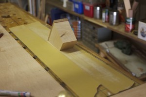
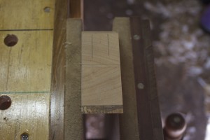
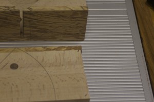
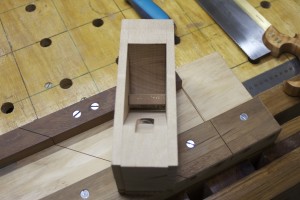
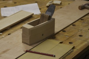
The next step is to start marking out the position of the toe and heel sections relative to each other. I started by marking out the position of the toe piece and clamping it into this position.

IMG_7181IMG_7182


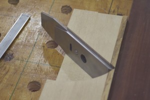
For the next step it is useful to have the blade in it’s position on the heel section, also known as the ramp. In the second picture you might just be able to see the line I marked at 1.5 mm parallel to the sole on the toe section. The idea is to line the cutting edge of the blade up with this line as demonstrated in the second picture. This tells you were the heel section should be relative to the toe section. You then remove the blade and mark the position with a pencil.

IMG_7183IMG_7184


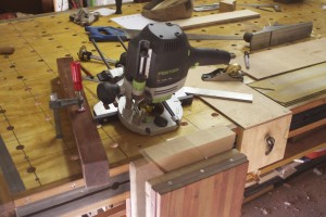
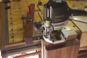
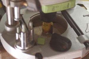
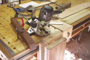
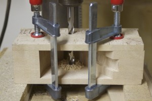
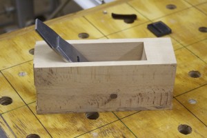
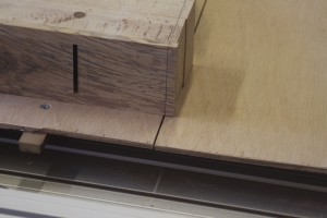
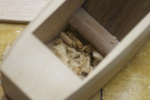
In the first two pictures below you can see where I marked out the perimeters of the cap-screw slot. The off-cut wedge is again priceless to create a big enough surface in order to cut the slot with a router as shown. Please note the makeshift stop I’ve setup on the left hand side.

IMG_7185IMG_7186IMG_7187IMG_7188IMG_7189IMG_7190IMG_7191IMG_7192IMG_7193


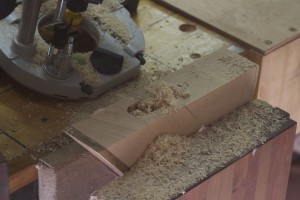
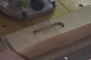
Just a quick test to see whether the slot functions as planed.

IMG_7196IMG_7197IMG_7198


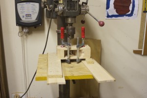
In order to drill the second of the cross-pin holes you need to clamp the whole shebang together after drilling the one side in the correct spot. You will find a host of different ways to identify this point on the internet. I used the measurements provided in an article titled “Wood Planes made easy” by David Finck in Fine Woodworking Magazine. Once I clamped it all into position I tapped some minute panel pins into each corner to ensure that I could put it all back together exactly in the same way during the glueing phase.

IMG_7199IMG_7200IMG_7207IMG_7210IMG_7208IMG_7212IMG_7215


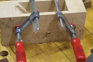
The idea is then to stick the drill bit through the existing hole to drill the opposing hole exactly in the correct place using a perfectly square drill press setup as shown.

IMG_7204IMG_7206


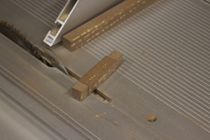
The cross-pin was created by milling a scrap piece of Assegaai down to a ½” square strip that was much longer than needed. In the pictures you can see how I removed some stock by means of the table saw to start shaping the pins on either side. In future I would rather do this with my Lie-Nielsen carcass saw. In the next few picture you can see how I shaped the pins with a file.

IMG_7202IMG_7203IMG_7216IMG_7217IMG_7220IMG_7221IMG_7222IMG_7223


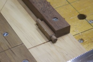
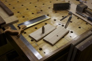
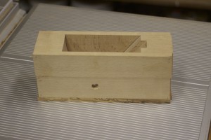
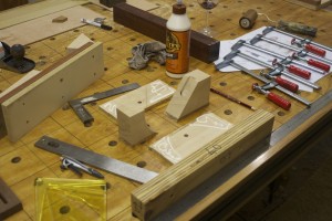
To make sure that everything fitted perfectly I did a dry fit as shown.

IMG_7224IMG_7225IMG_7226IMG_7228

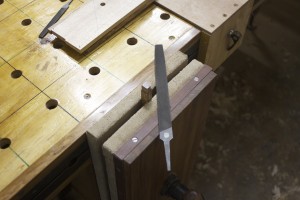
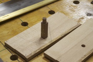
Then I shaped the cross-pin further by using this setup.

IMG_7230

The glue-up is fairly straightforward due to the panel pins that ensures that it all comes together precisely how it was previously decided. Please note the caul clamped to the sole area to ensure that it ends up perfectly aligned.

IMG_7231IMG_7232IMG_7234IMG_7236

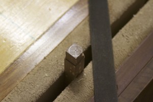
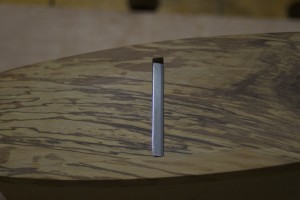
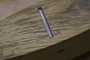
The cross-pins were then trimmed flush.

IMG_7273IMG_7274

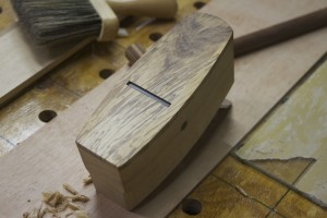
Next step was to shape the plane and I started by cutting the ends containing the panel pins away.

IMG_7275IMG_7277

Then I marked out this funky curvy configuration on the ysterhout sole. The reason for doing this on the sole was that I wanted to have the sole at the top while cutting the curves on the bandsaw to prevent blowout of the rocklike yet brittle ysterhout. In the second picture you can see the result of the bandsaw’s caress.

IMG_7278IMG_7279

The bandsaw marks were removed by a series of steps including the use of a float, a smoothing plane and finally various grids of sandpaper on float glass. The result was staggeringly beautiful to say the least.

IMG_7280IMG_7282IMG_7284IMG_7285

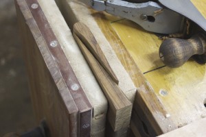
The piece of Tamboti you see in the pictures below is the only one I have left and a board I know as long as I can remember. I thought that this was the ideal place to use such a priceless piece of timber. I decided to produce the wedge of this sexy petite plane using Tamboti.

IMG_7316IMG_7317

Here you can see the wedge in it’s early stages.

IMG_7318IMG_7319

The next step was to decorate the plane further with some sexy stopped chamfers. I marked it out by hand using a pencil and my finger as a fence. You can probably see that I deliberately did not do a 45º chamfer, but rather one that further complements the elegant elongated shape of the plane.

IMG_7320IMG_7321IMG_7322IMG_7323

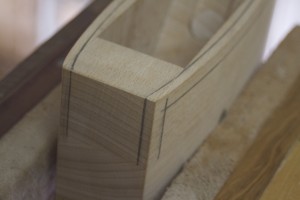
Using the pencil lines as guides I used a small Lie-Nielsen block plane, a file and my Proletarian Sanding Contrivance to create the chamfers.

IMG_7324IMG_7325IMG_7326

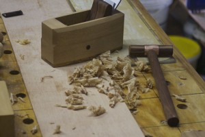
Then I moved on to flattening the sole. It is important to tap the wedge into position at about the same tension as it would be while being used, before attempting to flatten the sole. The pressure from the wedge deforms the sole ever so slightly so the idea is to flatten it in the shape it will assume while the wedge is tapped into place. You can see that I once again scribbled on the sole prior to flattening in order to identify when it is completely flat.

IMG_7329IMG_7330IMG_7331IMG_7332IMG_7336

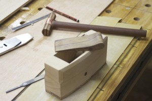
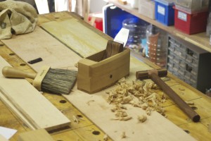
In order to custom-fit the wedge I dialed in the width by planing down the sides with my rehabilitated old Stanley no.4 Smoother. Apparently one should be careful not to make the wedge too tight-fitting as far as the wedge goes as it can damage the plane if it expands during humid months. I therefore made it about 3 mm narrower than the ramp. In the last of these three pictures you can see the plane hammer I built to set the plane. You will find an entire post devoted to this project under the category “Handtools”.

IMG_7333IMG_7334IMG_7335

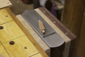
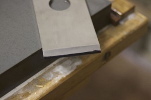
I sharpened the Lie-Nielsen blade to have a cambered edge.

IMG_7337

I took to a small piece of swarthout to test the little beauty and the results were incredible. It gave the best finish I have ever seen and the shavings were extremely thin and soft. There were not even a hint of chatter. What also surprised me was how easy it is to set the blade with the small plane hammer. It almost felt easier than setting a cast iron plane.

IMG_7338IMG_7339IMG_7340IMG_7341IMG_7353IMG_7351IMG_7349

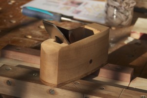
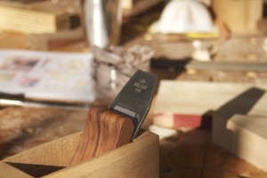
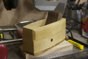
Here are two photos to show off the beautiful Lie-Nielsen iron-chipbreaker set.

IMG_7344IMG_7343

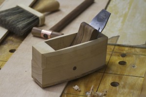
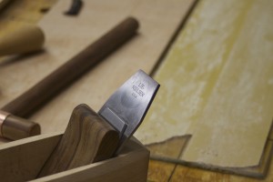
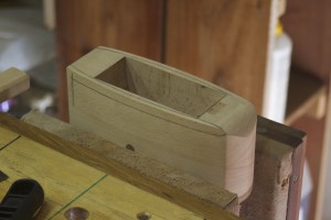
Part of the success of this little plane must be the tight mouth. In these pictures you can also appreciate the je ne sais quoi of the ysterhout sole.

IMG_7345IMG_7346IMG_7347

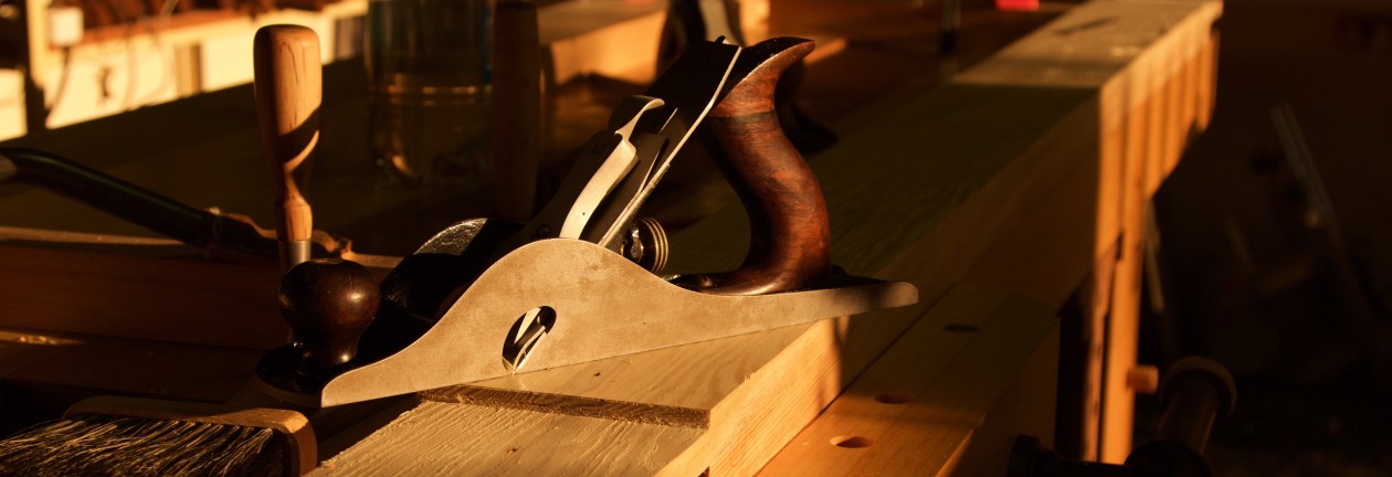
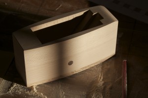
Finally a few pictures of the plane in the late afternoon sun after a light coat of Ballistol. I plan to treat the sole with wax once I find a suitable product.

IMG_7465IMG_7469IMG_7466IMG_7467IMG_7468


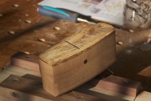
4/9/2013 – I finally got round to treating this little beauty after using it for a few weeks. You can see how it joined it’s bigger cousin at the Finishing Spa.

IMG_7916IMG_7917IMG_7920


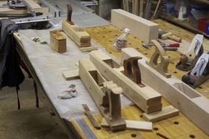
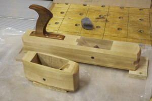
Here are a few final photos of a little plane that has already become a go-to tool in my shop within the space a month.


IMG_7931IMG_7933IMG_7934IMG_7923IMG_7924

F-Style Clamp tip

If you read my opus on the building and design of my assembly table you would remember that due to it’s relatively thin top the use of holdfasts are not an option for work holding through the multitude of dogholes. Therefore I came up with the following solution, which (to be honest) was simply borrowed from Festool on which most of the design of the table was based anyway. I modified Bessey F-style clamps so that one can take them apart in order to use them through the dogholes as shown below.

IMG_7070IMG_7045


Step 1: clamp it in a vise of some description.

IMG_7046


Step 2: use a relatively fine file to remove the metal that prevents the clamp from coming apart, as illustrated in the before and after pictures below.

IMG_7047IMG_7048


Plane Hammer

In this post we will briefly return to a state of “Mallet Mania”. As you might remember I wrote one of my first posts on the first four mallets I made and called it “Mallet Mania”. This past weekend I made the fifth in the form of a specialised plane hammer. It was necessitated by the fact that my first wooden plane was getting close to being finished.

I therefore squeezed in some time dedicated to the hammer necessary to set the blade of my Petite Smoothing Plane (post to follow in the near future). As per usual, even the bits and pieces that are available to use for such tools is quite limited in Namibia. In the pictures below you can see what I started with. It is one of those copper rings that plumbers use to join copper water pipes.

IMG_7238IMG_7248

I chamfered the inside edge of the one side with a medium sized file.

IMG_7245IMG_7246IMG_7247

Then I took a piece of Kershout and Witpeer I laminated for the handle of my legvise, that was left over and turned the head of the hammer (far right) together with three file handles while I was at it. It was turned in such a way that one side was similar in diameter to the outside of the copper ring and the opposite side slightly smaller than the inside diameter tapering up to sightly bigger than that. The idea being that one could tap the ring over to fit tightly.

IMG_7261IMG_7262

Here you can see how far the ring slid over the wood without any force. I applied epoxy to act as a lubricant and adhesive before tapping it into place.

IMG_7265IMG_7266

To ensure that the ring had nowhere to go I cut a thin curve to accept a very slight wedge, which was taped in after applying Gorilla PVA wood glue.

IMG_7269IMG_7288IMG_7271IMG_7272

The sides of this wedge were trimmed flush …

IMG_7287IMG_7290

… and cut to length as shown below.

IMG_7291IMG_7292IMG_7294


The next step was to mark out were to drill the hole for the handle. I used a compass to scribe a circle 2 mm bigger than the hole drilled for the pin of the handle in order to have a reference of how much I should enlarge the hole on this side to accept another wedge.

IMG_7295IMG_7296


In order to drill the hole accurately I made this quick jig out of scrap plywood. The hammer’s head sits steady in the groove and held in place by the drill press vise.

IMG_7297IMG_7298IMG_7299IMG_7300

IMG_7301IMG_7302


I used Kershout for the handle. Below you can see how I shaped the pin.

IMG_7303IMG_7304IMG_7305


Then I used a spoke shave, a rasp and a card scraper to shape the handle. It makes easy work of such a job.

IMG_7311IMG_7312


I then glued a small piece of sealskin to the one striking surface to give the option of a softer blow, when striking the wooden parts of the plane (as opposed to the plane iron).

IMG_7327IMG_7328


The final product prior to the usual Ballistol treatment.

IMG_7313IMG_7314IMG_7315


Tour de Shop 2011

I thought I should do a post from time to time showing photos of how my shop change over time. Sometimes this helps to remind you that you are actually making progress, when you look at photos of how the place looked like a year or two ago.

For this first edition of “Tour de Shop” I chose photos from the very first few months in this current shop, dating back to late 2011. At that stage we only just moved into the new house and my father arrived with a truckload of our stuff that was in storage in South Africa since 2002, while we were living in New Zealand. This shipment included all the tools (hand and power) that he passed on to me, and 17 cubic meters of Knysna Forest hardwoods that was dried naturally over a period of between 7 and 11 years. We bought the wood in batches between 2000 and 2004.

In the picture below you can see my initial makeshift workbench. It comprised three sawhorses with a sheat of plywood lodged on top. You can find an entire post on these sawhorse under the title “Darwinian Sawhorses”. To the right of the workbench you will see some makeshift tool storage. I refashioned the crates my Dad built to transport the tools safely into basic storage structures. It works well as everything is handy, but the only downside is that it gets quite dusty being completely open. The shelves on the left I found in another garage on the property and moved it. It is those made up of metal bars fixed vertically to the wall with adjustable horisontal arms on which the shelves rests. Over time this became the main storage for screws, bolts and all the other hardware.

100_0006

In the two pictures below you get a good example of my crate-converting-activities. My Father built this particular one to house the lathe during it’s odyssey from Outeniqualand to the Land of the Brave. I converted it into a cupboard that became the abode of all my finishing products.

100_0080100_0079

A quick reminder of the infancy stage of my assembly table. You can find a catholic five chapter opus on this project under the title “Alternative workbench/assembly table”, if you are intersted.

100_0032

The brackets that fixed my lathe to the wall were the first objects I have ever welded.

100_0010

Here you can see one of the first steps towards building up a comprehensive supply of fasteners and others hardware/supplies to prevent the problem of having to drive to the hardware store each time you need something. This is my old fashioned steel wood screws in almost all the sizes I might ever need.

100_0081100_0082

Phase two of the above, concerned bolts (standard and countersink heads), nuts (standard and lock), washers in heaps of different lengths but predominantly 6, 8 and 10 mm diameter.

100_0259100_0260100_0261

This was the first proper power tool I bought (ever actually), a Festool TS 55 circular saw with the table that is designed to also accept their router, etc etc. On the shelves to the right you can see the music system which I bought secondhand in New Zealand. I listen mostly to old vinyl  records, which I collect. Since discovering woodworking podcasts they also feature as part of my auditory diet. The green bench in the back corner used to be my father’s workbench. We will have a close-up look later in this post.

100_0005

The drill press I simply stuck on top of the crate it traveled in. One day I will build a better cupboard with storage for all the drill bits as currently I am doing a lot of walking to fetch them.

100_0012

The picture below was actually taken more recently, but I wanted to show you the red steel cupboard. My father bought this form his work when they got rid of such stuff and kept it disassembled in storage for many years. In 2000 I assembled it and painted it red. I used it for 2 years in the first shop I ever had and now it is doing duty in my current shop too. You can see how I pop-riveted scrap chipboard strips to the front of some of the shelves in order to contain smaller pieces of wood and steel. I sort off-cuts of wood in different sizes in the top three shelves and metal in the bottom three.

100_0008100_0702

The green cupboard is another survivor from many arduous years in my Dad’s workshop. I do not actually know it’s history (will ask the man and update the post), but it looks like it is a recycled kitchen cabinet (from the 70’s as per fashion trends) and I painted it green in 2000. On the doors above the work surface you have the added benefit of appreciating my 4 year old daughter’s art.

IMG_5900

This became my metal working area. The green (not my doing, incase you think I am a Greenie) steel structure with the steel vise was created by my father many years ago. On the crate/cupboard next to it, I have hung the bits and pieces of metal working tools I have. In the mentioned cupboard you might notice the red welding machine (not quite sure what it is called to be honest). I bought this one and am trying to teach myself this skill. The massive black pipe on the right is a chimney I fashioned for a Pizza wood oven we built immediately outside our kitchen.

100_0839

These shelves were already in the garage when we bought the property, which was an monumental gift.

100_0009

Below you can see just another example of how I converted the crates into storage by adding shelves. In this case some tools hang on it’s side, the top shelve house painting paraphernalia, the next one down, all the sanding bits and pieces (including the two old Stanley planes pre-rehabilitation) and further down quite a few Stinkhout legs (from my father’s collection).

100_0704

Finally, the green bench which served the previous generation of Marx cabinetmakers for innumerable years. I stuck it in this corner, close to the lathe and drill press. On the wall you can see the “Darwinian Sawhorse” I wrote a whole post on under the same title.

100_0011

Epoxy tip

I find that 99% of the time I need minute amounts of Epoxy at any one time. Seeing that Epoxy is not as easy to cleanup as PVA glue I came up with the idea to mix these smatterings of adhesive in  soft drink bottle caps. In the pictures below you can see how I collect some in an empty water bottle for this purpose.

IMG_7088IMG_7089

In the example below I used a beer bottle cap. I throw the caps away after use, which eliminates the needs to clean up.

IMG_7087IMG_7085

Reprobate Sealskin Strop

This is a straight forward hand tool that some might argue to have become obsolete, especially since the advent of devilishly fine waterstones used in conjuction with Nagura stones. However, to me it reminds of the days gone by, which creates a sense of being part of the traditions of the craft.

That is why I fashioned this sealskin strop. Before all the whiny greenies get on my back, I did not kill any seals for this purpose. I simply bought the skins at Nakara. As far as I know, Namibia has been involved in a sustained seal genocide to which more liberal societies have developed an aversion of note. As I see it, these seals were well and truly dead by the time I bought the skins, so I might as well honour their expired existence by creating a timeless heirloom tool with it. Come to think of it, in the light of the above I should probably warn sensitive readers that this post might contain disturbing images, if you are that way inclined.

As per usual I found a small piece of Assegaai for the job. The bandsaw was responsible for the rough shaping, before I took to it with a few files to round the areas forming the handle.

IMG_6930IMG_6931

I then used a card scraper to remove the file marks, which I can really recommend. It works like a charm for this purpose, as you can see from the pictures below.

IMG_6989IMG_6990

The area that would end up covered with sealskin, were then planed flat with a rehabilitated old Stanley Jack Plane. I wrote a comprehensive post on this particular endeavor, which you will find under the category of “Rehabilitation of old tools”.

IMG_7091IMG_7092

To make absolutely sure it was flat, I used 3M adhesive-backed sandpaper on glass to get it as close to perfect as possible. I used the technique of scribbling on the wood with a 2B pencil before sanding to identify the low spots. The job is done once all the pencil marks has disappeared as you can see in the last picture. I advise those sensitive types to stop reading at this point.

IMG_7093IMG_7095IMG_7097

Two sealskins as bought from Nakara. In the closeup picture you can appreciate that the leather is quite rough, which is probably wicked for this purpose.

IMG_7098IMG_7099

A magic marker was used to trace out the strips needed.

IMG_7100

I first glued the narrow strips to the sides …

IMG_7101

… then the wider strips.

IMG_7118IMG_7119IMG_7120

I used a very sharp chisel to remove a few untidy strips of leather and …

IMG_7125IMG_7126

… finally the usual treatment with Ballistol gave the Assegaai a beautiful sheen.

IMG_7128IMG_7127

Bandsaw Mitre-sled

I am in the process of building a series of wooden handplanes. Due to the fact that I cannot buy timber in dimensions that would allow construction from a single piece, I have to follow the method of laminating made famous by James Krenov. Unfortunately, this necessitates a fairly functional bandsaw given the dimensions of these planes. My bandsaw is of a Chinese persuasion that few people peregrinating the so called western world (including myself) would have heard of before. I always though that was how a bandsaw should look like as I have never seen another until I started reading a bit more about woodwork.

Every expert these days seems to advocate for using the bandsaw in a way that the table saw used to be in years gone by. I first thought they were mad as my bandsaw could not even cut a smooth curve leave alone rip and re-saw and all these absurd new tasks they suggested should be done with it. Then I had a look at how these bandsaws looked like and realised that they were quite a bit different to mine. In the first place, the operators actually tuned the contraption before going to war with it. I did not even know that it could be tuned. I then watched a video by Michael Fortune on how to do this. It is on the Fine Woodworking website (member’s section if I remember correctly).

Anyway, this is all a bit besides the point. Point is, I spent a significant part of a week on rehabilitating my bandsaw, which included the process of building this jig that I call a “Bandsaw Mitre-sled”. I plan to write a post on the actual rehab process of the bandsaw in the near future.

The owner of a local tool shop by the name of Martin Mozny (Windhoek Tool Centre) gave me a whole heap of Festool equipment that was apparently used for demonstrations and therefore not in a condition to be sold as new. Despite this the stuff is in top order, especially for building jigs. While contemplating the design of this jig I consulted the container that house the orphan Festool bits and pieces. I considered both of the parts in the below pictures, but decided to rather use another.

IMG_7033IMG_7034

Here you can see the the mitre gauge I decided on together with a piece of scrap plywood that would become the main parts of the jig.

IMG_7035

Next I found some scrap pine and swarthout (not in the picture) to form the edges/aprons. A strip of Harde Peer left over from another job was shaped first on the table saw, then the thicknesser and finally handplaned to fit perfectly in the channel/dado in the bandsaw table.

IMG_7036IMG_7037

Here you can see how I have set up a temporary fence to drill the holes for attaching the strip of Harde Peer and the Festool mitre gauge. The strip was then glued and screwed to the plywood.

IMG_7042IMG_7043IMG_7044IMG_7060

In the pictures below you can see the profile of the aluminum arm of the mitre gauge. The bottom of the profile is fairly thick, which allowed me to drill 5 mm holes in order to cut thread for a 6 mm bolt.

IMG_7038IMG_7039IMG_7040IMG_7041

Here you can see how I drilled the holes on the drill press …

IMG_7049IMG_7050IMG_7051IMG_7053IMG_7052

… and cutting the thread.

IMG_7054IMG_7055IMG_7057IMG_7058

The mitre gauge was then fixed to the plywood with three countersink bolts.

IMG_7061IMG_7062

As you can see these bits of scrap pine has done duty in several other incarnations. The swarthout in the centre had less battle scars. I then processed these pieces to assume the same dimensions.

IMG_7064

In the first picture below you can see how I removed a small area of the swarthout to accept the harde peer strip. I also used dividers to quickly mark out all the screw holes that needed to be drilled in the plywood to attach the sides/aprons.

IMG_7065IMG_7066

After drilling the mentioned holes I clamped the sides and plywood into place as shown. In the third picture you can see how useful a cuff can be to restrict the depth of the pilot hole to exactly the length of the screw.

IMG_7067IMG_7068IMG_7069IMG_7070

The next step was to tidy up the wooden parts of the jig. Yes, you are right I did remove the mitre gauge to make this a bit easier. You can also see how handy my “Proletarian Sanding” Contrivances are in these situations. You will find an entire post devoted to the building of these sanding planes, under the category Handtools.

IMG_7071IMG_7072IMG_7073

The mitre gauge goes back and the jig is ready to cut the zero clearance curve …

IMG_7074IMG_7075

… like so …

IMG_7078IMG_7079IMG_7080IMG_7081

The first cut I made using this jig was a 51º bedding angle on a blank meant to become a small smoothing plane. It was made up of Beech with an Ysterhout sole. One unexpected advantage of this jig I discovered was that the zero clearance curve tells you exactly where the cut will be made. If for example you mark it out on the stock as I did on the plane blank, it becomes extremely easy to position the stock for a perfect cut …

IMG_7146IMG_7147IMG_7148IMG_7149

… as shown in the pictures below.

IMG_7150IMG_7151IMG_7152IMG_7153