A Table for a shebeen – part 3

16/11/2016

The year is hurrying towards it’s inevitable end and the temperatures in my tropical haven are racing upwards at the same rate. The massive shift in ambient humidity that a good rainy season can induce always wind me up to get joinery that is supposed to last a really long time assembled during the driest part of the year. In my case that means before the end-of-year holidays, as the proper electric storm driven downpours tend to ignite a sudden hike in humidity around mid January. That is of course if we are lucky, because water has been in short supply in this sweltering savanna of ours.

For the purpose of this project I wanted to get the two leg-assemblies done before we leave for a hitherto tranquil spot on the Azanian south coast. Unfortunately the Zuptopian conglomerate has since done it’s utmost to “poison and destroy my brothers”, but let’s not dwell on the bane of my life while we could be discussing woodwork.

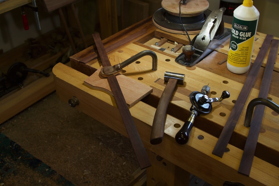
As discussed before, I prefer using Assegaai for my custom made drawbore pegs. I usually try and find a perfectly straight-grained piece before ripping strips on the table saw that are then fed to my Stanley no. 77 dowel making machine (not pictured). Unfortunately it is pretty much impossible to split (as apposed to rip) stock along the grain then using the no. 77 as you need perfectly square strips, but if you use fairly straight stuff it still turns out dowels that are far superior to the rubbish bought in local stores. I wrote in more detail on this process in previous posts.

img_7709img_7712

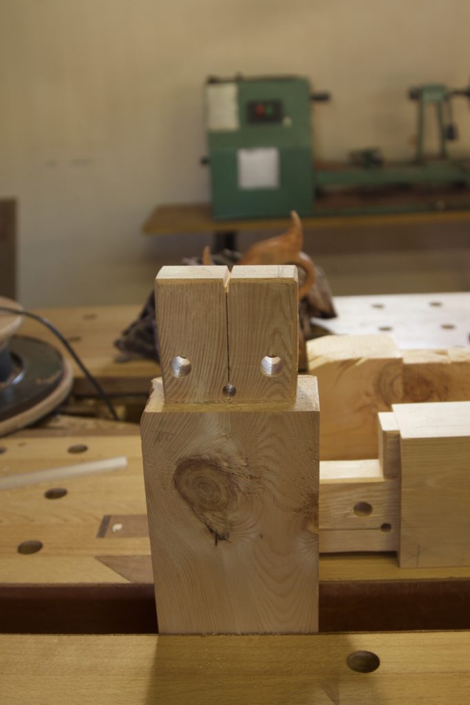
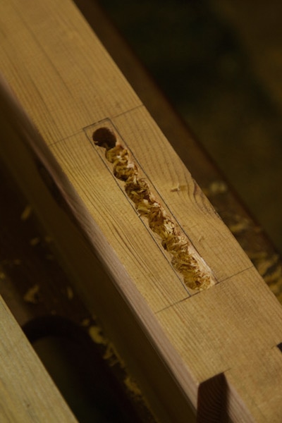
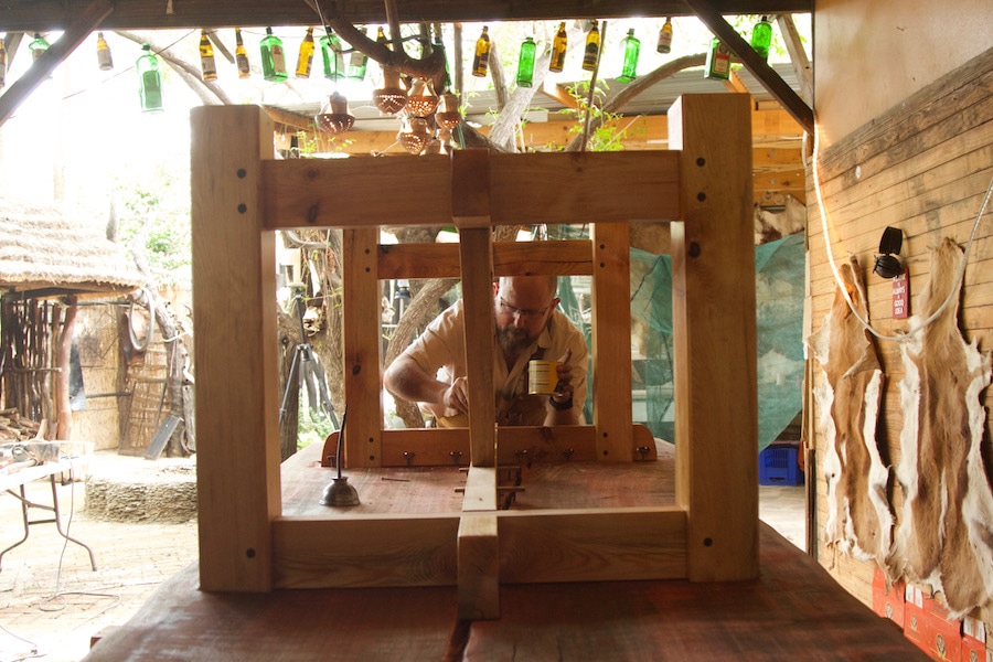
For the sake of trying something new I decided not to go with wedged through tenons as I did with the two workbenches that was built with similar sized stock. I am however partial to the idea of using wedges to ensure maximum strength. Therefore it was decided to experiment with wedges in a closed mortise. You will notice the kerf prepared for the wedge in the monstrous tenons. The sides of the mortise that needs to allow for the wedge to expand the tenon were adjusted. Then it is simply a matter of positioning the wedge in such a way that it sits in the entrance to the mentioned kerf while using pipe clamps to coerce the tendon into it’s mortise. That is of course followed by tapping the drawbore pegs home while the clamps are still in situ. The pictures below also show how I used my Festool Domino to cut the slots for the bits of wood that will fix the aprons to the top.

This was how the two leg-assemblies spent their festive season.

img_7713img_7714

16/1/2017

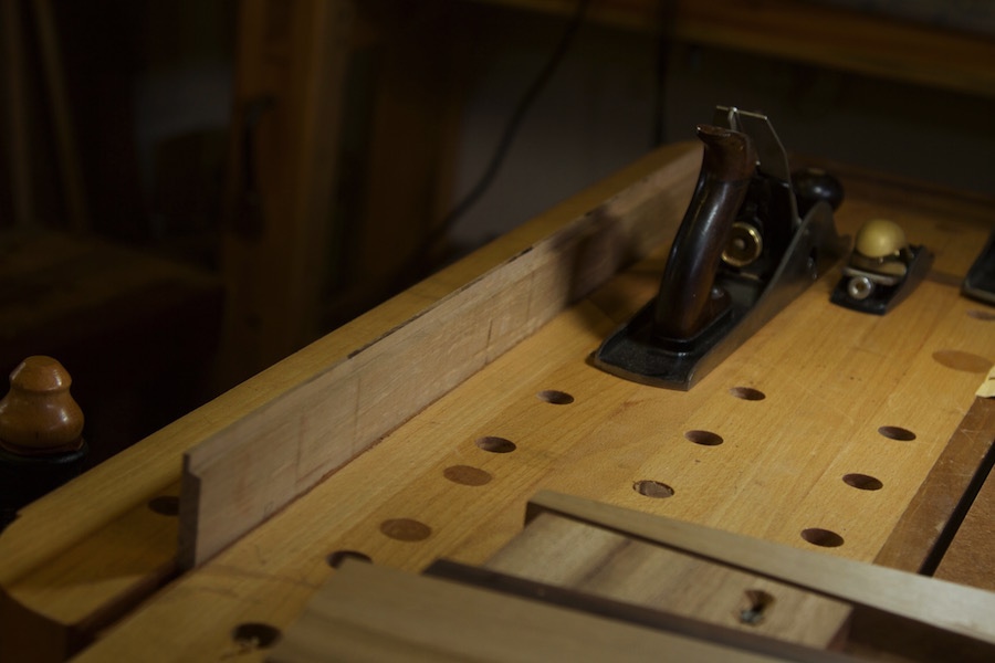
The drawbore pegs were then worked flush by sawing and hand planing.

IMG_7787IMG_7788IMG_7789IMG_7790

In order to mark out the exact location of the tenons of the two beams that link the two beams between the leg-assemblies (at an angle), I had to assemble the undercarriage.

IMG_7797IMG_7798IMG_7799

By clamping the linking beams at exactly the right angle, I was able to mark out the shoulders of the tenons.

IMG_7800IMG_7805IMG_7804

For some reason I found it very difficult to keep to the marked out lines while sawing away the waste by hand. It was the first time that I encountered this problem and still do not know exactly what was going on as I have done many similarly sized tenons in the same wood with the same saw?? Therefore I switched to the bandsaw for the rest of the work.

IMG_7806IMG_7807IMG_7808IMG_7809IMG_7810

I usually like to saw close to the line and hone in on it by planing the cheeks to a perfect fit.

IMG_7815IMG_7816

Marking out the location of the mortises.

IMG_7817

15/3/2017

Drilling out waste.

Removed the rest of the waste by vertical chopping.

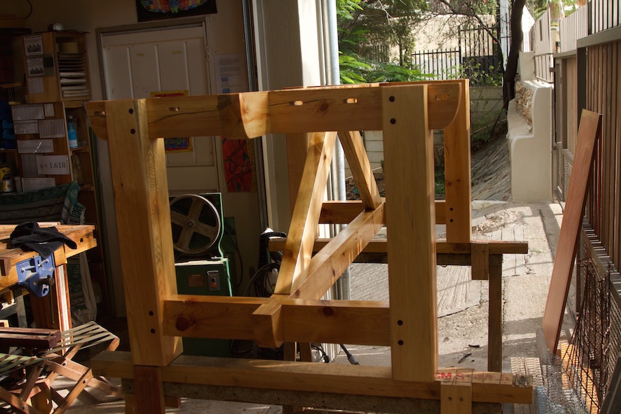
Then it was time for the final glue-up of the undercarriage. I was very happy with how it came together and it sure is a robust construction.

The undercarriage received a few layers of Woodoc.

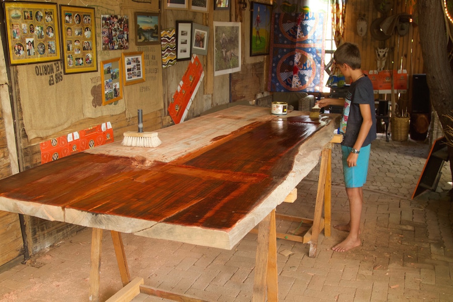
Before installing the undercarriage, the bottom of the top received a few layers of boiled linseed oil.

The pictures should do a better job than words to explain how the top was fix to the undercarriage.

Once that was done it became time to bring in some strength to get this baby to it’s feet.

Now I have to flatten the top by hand and trust me it looks a lot flatter than it is in the pictures below. I hope to complete this task before the end of the year.
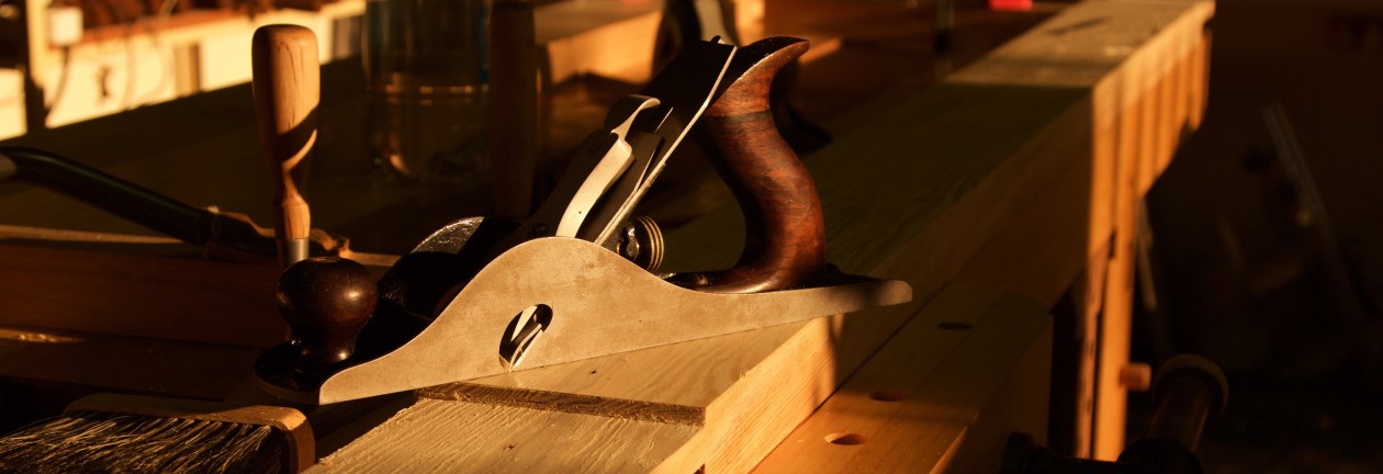
North Brothers venturing south – PG

17/1/2017

No, this is not the title of a cheap porn movie aimed at the well known niche market for this particular genre of cinematic gems amongst serial tool collectors. The whole family should thus be able to digest this post, however JNSQ Woodworkings refuse to be held responsible for any unforeseen ailments that might result from indiscriminate consumption of the material. Parental guidance is therefore advised.

On a more serious note, I would like to apologise to my great friend, fellow blogger and tool historian par excellence Robert “Bob’s your Uncle” Demers for not posting this much earlier in the year. After all he found me a freakin legendary example of 20th century American tool manufacturing.

After using a couple of different examples of eggbeater drills it became apparent that my stockpile of African hardwoods necessitates contrivances with either massive drive wheels or a favourably geared two speed setup or ideally both. To give you an example, my first eggbeater was a Wiktor Kuc restored 1938 edition Miller’s Falls no. 2. It is supposed to be an ideal allrounder for the frugal (more recently known as “anarchical” in the prevailing Schwarzian vernacular) woodworker, but it really struggles to drive anything larger than a ¼” bit in lumber from the Dark Continent.

Initially I thought this is simply how it is with these eccentric drilling apparatuses, until by sheer chance I happened to stumble upon a two speed no. 5½ B Goodell-Pratt with a positively massive drive wheel. These babies know how to roll, innit. The GP has more torque than my 8 year old daughter, except in her case it is spelled slightly different.

Given this revelation I set out to procure another torque-ative eggbeater to torment my hardwoods with. Bob was of course my first port of call and I explained my predicament in some detail. You can read his summation of the tool here, which (by the way) is a hell of a lot more informative than this post. He agreed to keep his well educated eye out for a suitable monstrosity. It did not take him long to find Utopia in the form of a two speed North Brothers no. 1545.

Bob refused that I reimburse him for the tool or the shipment cost and sent it on it’s merry southward journey at the end of 2016. Luckily it did not embark upon a protracted sub-Saharan voyage like a particular parcel several moons ago.  It arrived somewhat promptly, for trans equatorial pilgrimages, in mid January 2017. I did return the favour by sending him a locally made hammer, but clearly I received more value than he did.

It is only my second true North Brothers tool (as apposed to Stanley made attempts) and completely lives up to my very high estimation of this famous tool manufacturer. The low gear munches through anything Africa can throw at it and the considerable weight lends some advantageous momentum to drive wheel as well as a general feeling of old school quality.

The no. 1545
The NB no. 1545 with the GP no. 5.5B
The NB no.1545 with a 1938 edition MF no. 2
The NB no. 1545 with it’s smaller cousin the no. 1530


I took the drive wheel off and cleaned everything I could reach. It presently purrs like a cat on crystal meths.

Thank you Uncle Bob I will cherish this gem as long as I have the privilege to do so and hope to pass it on to someone who will continue to do so long after both of us joined the choir invisible.

My second commission – part 10

15/3/2017

My dear reader, I would like to apologise for my extended absence from the wonder world of virtual woodworking via the internet. You would find the reasons quite boring so let’s not waste any time nor effort ruminating on such drivel. This instalment of an apparently mammoth series will concern itself with the addition of the third and final layer of the so-called trapezoid leg. You can find earlier posts in this series here.

Seeing that the third layer would ultimately close up the internal workings of the whole construction, I took the opportunity to unscrew the second layer’s three ‘cross members’ (for lack of a better term). As you should be able to observe in the photos below, the old school mild steel wood screws received a coat of beeswax. This was accomplished by melting a block of wax in a small tin containing these traditional fasteners. The idea with this is that the wax should reduce the effort required to seat the screws and at the same time providing a layer that would resist future corrosion.

The screws were then seated after the surfaces that is supposed to be able to slide ever so slightly with the changes in ambient humidity over the years, were rubbed with beeswax. Whether this is useful (or possibly the opposite) I do not know, but I tried it anyway. Therefore I would urge you to ask someone who knows before following suite. Maybe some of our more experienced and properly trained cadres could assist in the matter.

Seeing that the plan was to fix the third and final layer using panel pins I had to fashion a custom punch to seat the nails below the surface of the wood. A short section of a round file which I picked up somewhere served perfectly well for this purpose. It was shaped carefully (not to take the temper out of the hardened steel) on a bench grinder to fit the head of the panel pin to a T. There are some picks further down to show the business end of my new redneck punch.

As is so common here in Africa, I also had to modify the panel pins somewhat to serve my purpose. In order to allow layer one and two to be able to move relative to each other, these panel pins had to stop short of layer one. In other words they should only fix layer three to the cross members of layer two. That was accomplished by snipping off the required amount, followed by resharpening on the bench grinder.

The two Kershout strips were fitted first, as they needed to be absolutely spot on given the fact that they mirror the spindles of the so-called Windsor leg. Kershout seems to enjoy spending time off  the Janka hardness charts (literally and figuratively) so it hard to say where it rates in comparison to better known species, but let’s just say it tends to take exception when a nail wants to upset it’s feng shui. For that reason I had to drill shank holes for each panel pin, which allowed the shank through and only caught the slightly wider head. This way the panel pins were more inclined to retain it’s linear configuration and the Kershout refrained from flexing it’s muscles.

As discussed in earlier posts, the third layer only needs to add another 8 mm for the trapezoid leg to reach it’s intended thickness of 44 mm. Therefore I decided to challenge my new bandsaw with fairly wide re-sawing in very hard Witpeer. Of course that also allowed me to introduce visual interest by means of a book-matched arrangement of the various pieces.

In order to do that I needed one flat, square and twist-free face side and face edge.

The resultant 8 mm stock were then fitted from the centre of the leg towards the outside. I again used the hitherto unproven technique of rubbing beeswax on the surfaces that is supposed to be able to slide.

I used a no. 78 and a no. 10 Stanley rabbet plane to cut the rabbets that hides the space allowed for movement.

The book-matched pattern is already vaguely apparent.

All the sides were then worked flush.

By hand plane along the grain …

… and by track saw followed by hand plane across the grain.

The small cavities created by seating the panel pins below the surface of the wood were filled with a concoction conjured up by mixing very fine wood dust (of the same wood of course) and epoxy.

Once the elixir had time to set I did a preliminary round of surface preparation.

As you can see the book-matched pattern is starting to emerge nicely. Once it receives oil it should be positively stunning.

Even the opposite side is starting to display a certain je ne sais quoi.

The edges were then treated to some hand beading to hide the laminations.

As you can see it worked a charm.

In our next instalment we will move on to laminating the various boards that was chosen (many moons ago) for the top.