Tag Archives: ysterhout

The lumbering odyssey

In this post I would like to document the long and arduous odyssey of the wood I love so much. As I have explained in previous posts such as “My journey 3”, I feel a special connection with the wood from the area where I grew up. The ancient hardwood forests of the Southern Cape is were I feel most at peace as a person. I love the the smells, the sounds and the cool  damp atmosphere.

It is from these forests that I bought small batches of wood with every cent I could spare at the auctions they used to have there. They used to cut trees that are more than 80% dead in their crown and then auctioned them off once per annum. Apparently, even this activity has been discontinued since 2005.

It used to be my favourite day of the year, getting up in the early hours of the morning to prepare for battle. I used to pack some biltong, a few sandwiches, coffee, a bottle of Calitzdorp’s finest port and head off to the forest to tussle with the big furniture companies (with even bigger checkbooks) in order to secure a few logs. Over a period of 2 years (2000 and 2001) while living back in my hometown, I personally attended and bought wood from two of these auctions. On the second of these auctions I was accompanied by my father, my wife and my cousin. We had an absolute ball of a time and secured quite a few logs. My father then attended two more auctions on my behalf while we were living overseas. We managed to accumulate 17 cubic meters of mainly Assegaai, Ysterhout, Witpeer, Harde Peer, Kaapse Swarthout, Kershout and Wit Els.

21/11/2013 – Last night I found this piece of paper documenting what I bought over the mentioned time. My father must have drawn it up in order to get the clearance to transport the wood to Namibia. There are a few mistakes, but at least it reminds me exactly when what was bought. 

hout koop lys

Once you buy the logs you have to arrange to get them removed from the forest and sawn to your liking. My logs were always processed by a lady by the surname of Botha. In this part of the world Botha is similar Smith in England. My mother’s maiden name was Botha to give you an idea. Anyway, this Botha lady did a great job every single time.

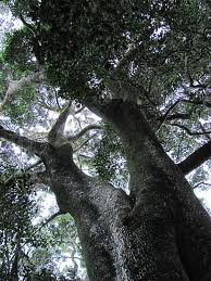
In the pictures below you can get an idea of how these trees look like in the forest. The wood is (in almost every case) extremely hard and takes literally several hundred years to grow to the size needed for furniture making.

ysterhout boomysterhout baswitles1_Assegai_tree_-_Curtisia_dentata_-_afromontane

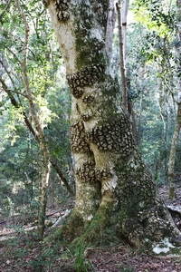
The Knysna Loerie is a shy yet glamorous resident of these forests.

slide-Knysna-Loerie-in-Forest-3eos11978_327wKnysna-Turaco-20110424

The wood then went straight into this garage stacked with spacers (as shown) without any artificial drying. It sat in this exact position for between 6-10 years (depending on the batch) in a coastal environment at a fairly high ambient humidity. As you can see, my father did a great job of stacking the wood for slow yet consistent drying. By the way, you will notice the baby on the wife’s arm. This is my son Didi whom you would have met in earlier posts masquerading as Pai Mei.

2006_0119DesVakansie200502222006_0119DesVakansie200502242006_0119DesVakansie200502252006_0119DesVakansie200502262006_0119DesVakansie20050228

Thought you might need a quick reminder of who Pai Mei is. If you are still intrigued watch “Kill Bill”.

pai mai 2pai mai

At the end of 2011 we bought a house in Windhoek and moved all our earthly belongings 1800km. The wood that was very much stable at the coastal humidity at that time were stacked without pacers as shown below. I decided to stack it this way for two reasons. One, I did not have enough space at the time, and two, in an attempt to slow down the drying process moving from high to low ambient humidity. I also kept a few 20 liter buckets full of water in the garage and did not open it much at all for the first year in a further attempt to slow down the drying. Whether it was as a result of these measures I do not know, but the wood really settled down very well.

100_0118100_0119100_0121100_0120

I will add the last stage (hopefully) of the odyssey, which should take place in the next few weeks to a month. I am in the process of preparing their longterm home. The idea is to have them under a roof shaded by many big trees in racks sorted by species. Here are the most recent pictures I have of their future home. You can see the carcass of the, soon to be, tin roof hiding under several large trees. It is an area of around 20 square meters in total. I hope to have my prized lumber ‘kickin’ it in the Caribbean’ (so to speak) under this roof by the end of this month.

IMG_7594IMG_7591


19/8/2013 – I took these photos on the weekend of the rough structure my father-in-law built in order for me to be able to sort the 9 odd species of wood into separate “boxes”. Now we need to first wrap the area with shade net and black builders plastic in order to keep the sun off the wood and create an optional enclosed area in order to regularly fumigate the stack of wood.


IMG_7612IMG_7613IMG_7614

18/10/2013 – A week ago my friend Sigmund and I started to add a sprinkling system to this wood storage facility. You will also notice that all the wooden structures have been painted with a 50/50 mixture of diesel and oil recycled from vehicles, as provided by my mechanic who filled a 20 litre can for me in only 2 days. The idea is that if and when the riverbed vegetation bordering this structure goes up in flames, (as what tends to happen during the last few months prior to the first rain as lit by thunderstorms) I could open one tap and the area around the shed and the wood in it would be soaked in water within minutes.

IMG_8386IMG_8388IMG_8389IMG_8390IMG_8391IMG_8392IMG_8393IMG_8394

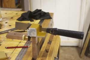
8/2/2014 – We finally managed to move the lumber into it’s cosy wee home today. Almost the whole family (Didi, the wife and I) and four chaps from Oshiwambo extraction (including our own Tobias) worked very hard for more than 5 hours on the trot to get the job done. We had a system going where the wood first ended up on the saw horses for me to code it according to species. Then it was moved to it’s new home to be stacked in piles according to the species.

IMG_9643IMG_9641IMG_9642

Here you can see a ‘Y’ on a board, indicating that it is Ysterhout.

IMG_9645IMG_9649IMG_9650

The wife enjoyed her gym session with a vengeance.

IMG_9654IMG_9655IMG_9656IMG_9661IMG_9657IMG_9659


IMG_9671

Didi got tired of carrying wood and decided to become the event photographer.

IMG_9707IMG_9708IMG_9711


IMG_9722IMG_9725IMG_9810


At this point we decided to have lunch. As you can see we made good progress.


IMG_9832IMG_9834IMG_9835IMG_9836


Lunch came in the form of a proper Africa braai, which Didi managed with quite a bit of encouragement from his mother.


IMG_9838


My precious wood finally came to rest in it’s purpose-built shed after 10-14 years (depending on the batch) in various different storage facilities and close to 2000 km of traveling!!


IMG_9856IMG_9857IMG_9858IMG_9859IMG_9860IMG_9862IMG_9863IMG_9864

Petite Wooden Smoothing Plane


I have been reading about and planing to make my own wooden planes for about a year now. I first thought of the idea when I realised how expensive it is to order good quality planes from the USA. For every two Lie-Nielsen planes I pay for an extra one in shipment fees. Make no mistake, the people at Lie-Nielsen have the best customer service I have ever come across and as everyone knows their planes are superb. Yet, sending it half way around the globe costs money.

The more I read about the wooden versions, the more it sounded like they might almost be better than their heftier cousins. Being a bit of a traditionalist, the idea of building my own wooden planes started to gain some momentum. I then had discussions with Deneb Puchalski of Lie-Nielsen around which blades might be best for the types of planes I wanted to build. He was very helpful and in the end I decided on:

1) Three x 2″ wide standard blades with chipbreakers (25 degree primary bevel)


2) One 1¾” wide standard blade with chipbreakers (25 degree primary bevel)


3) One Scrub plane replacement blade 1½” x 3/16 (thick)


4) One large shoulder plane replacement blade 1¼” x 8¼” x 0.140″ (thick)
The blades arrived on the 11th of June 2013 at which time I started to hunt down beech. Surprisingly, I found some in the Land of the Brave. I decided to first build a smoother and a scrub plane to warmup.
In the pictures below you can see the first chunk of beech after it received attention from the planer.

IMG_6906IMG_6907

At this point in time I still did not rehabilitate my bandsaw (thus not able to re-saw at all and definitely not ysterhout in any dimension approaching what was needed), so I had to plane a fairly small piece of ysterhout down to about 8 mm thickness (from about 24 mm). I wanted to use this incredibly hard wood for the soles of my planes. In the pictures below you can see how I used the bandsaw to cut the sole of the smoother.

IMG_6932IMG_6933

After studying the grain of the beech I decided to laminate it as you can see in the pictures below. It is impossible to find beech in bigger dimensions (around these parts) so lamination was my only option. Speeaking of which, I can really recommend the documents on building wooden planes written by Larry Williams and his partner at Old Street Tools. You will find the link on the library page of this site. There are articles on grain orientation, best woods to use etc etc.

IMG_6935

Here you can see how I laminated the parts.

IMG_6937IMG_6938IMG_6939IMG_6940

For some or other reason I decided to stick it in the face vise, which is not the best as the two jaws are not completely parallel, and I have made this mistake before. Anyway, it came out OK, but I really need to stop doing this.

IMG_6943IMG_6944

Next step was to hand plane the sides dead flat and square to the sole. You can appreciate the beautiful soft shavings generated by my newly rehabilitated Stanley no.5 Jack Plane. I wrote a complete post on this project which you can find in the category by the name of “Rehabilitation of old tools”.

IMG_7010IMG_7007IMG_7012

In order to make the next cut I was forced to spend most of the next week trying to fix and tuneup my old crappy bandsaw. The results however made it well worth my while. After the tune-up it sliced such perfect strips off the side that it only took a few strokes with the plane to get them as smooth as a baby’s bottom …

IMG_7031IMG_7024IMG_7032

… as you can see here.

IMG_7133IMG_7134IMG_7135IMG_7136

I then used the planer/thicknesser to get the inside close to the correct width. Maybe a bit less than 3 mm wider than the width of the blade. For this Petite Smoother I chose the 1¾” blade.

IMG_7142


Here you can see how I marked out the bedding angle at 51º (just to be different of course).

IMG_7144IMG_7145

In order to make this next cut I had to build a jig for my bandsaw. I call it a “Bandsaw Mitre-sled”. You can find and read an entire post on this project under the above name …

IMG_7146IMG_7147IMG_7148IMG_7149

… here you can see the actual cut.

IMG_7150IMG_7151IMG_7152IMG_7153

In the first picture you can see the toe and heel section after the first cut. In the next pictures you can appreciate the curve that was cut in the toe section.

IMG_7154IMG_7156IMG_7157

I used the Green Monster to smooth the curved surface of the toe section.

IMG_7158IMG_7159

In order to prevent blowout of the Ysterhout sole while planing the so called ramp, I used the wedge (off-cut) that was created by the two cuts made earlier. You can see how I clamped it in the legvise to support the fibers on the delicate edge of the sole.

IMG_7167IMG_7168IMG_7169IMG_7170IMG_7169IMG_7171


After getting rid of the saw marks left by the bandsaw by means of the old Stanley Jack Plane I used the 3M Adhesive-backed sandpaper on a sheet of float glass to get it 100% flat. You will note the technique I use frequently in scribbling on the area with a 2B pencil before sanding to identify the areas that needs more attention. Once all the pencil marks disappear you know the job is done.

IMG_7172IMG_7173IMG_7174IMG_7175IMG_7177


The next step is to start marking out the position of the toe and heel sections relative to each other. I started by marking out the position of the toe piece and clamping it into this position.

IMG_7181IMG_7182


For the next step it is useful to have the blade in it’s position on the heel section, also known as the ramp. In the second picture you might just be able to see the line I marked at 1.5 mm parallel to the sole on the toe section. The idea is to line the cutting edge of the blade up with this line as demonstrated in the second picture. This tells you were the heel section should be relative to the toe section. You then remove the blade and mark the position with a pencil.

IMG_7183IMG_7184


In the first two pictures below you can see where I marked out the perimeters of the cap-screw slot. The off-cut wedge is again priceless to create a big enough surface in order to cut the slot with a router as shown. Please note the makeshift stop I’ve setup on the left hand side.

IMG_7185IMG_7186IMG_7187IMG_7188IMG_7189IMG_7190IMG_7191IMG_7192IMG_7193


Just a quick test to see whether the slot functions as planed.

IMG_7196IMG_7197IMG_7198


In order to drill the second of the cross-pin holes you need to clamp the whole shebang together after drilling the one side in the correct spot. You will find a host of different ways to identify this point on the internet. I used the measurements provided in an article titled “Wood Planes made easy” by David Finck in Fine Woodworking Magazine. Once I clamped it all into position I tapped some minute panel pins into each corner to ensure that I could put it all back together exactly in the same way during the glueing phase.

IMG_7199IMG_7200IMG_7207IMG_7210IMG_7208IMG_7212IMG_7215


The idea is then to stick the drill bit through the existing hole to drill the opposing hole exactly in the correct place using a perfectly square drill press setup as shown.

IMG_7204IMG_7206


The cross-pin was created by milling a scrap piece of Assegaai down to a ½” square strip that was much longer than needed. In the pictures you can see how I removed some stock by means of the table saw to start shaping the pins on either side. In future I would rather do this with my Lie-Nielsen carcass saw. In the next few picture you can see how I shaped the pins with a file.

IMG_7202IMG_7203IMG_7216IMG_7217IMG_7220IMG_7221IMG_7222IMG_7223


To make sure that everything fitted perfectly I did a dry fit as shown.

IMG_7224IMG_7225IMG_7226IMG_7228

Then I shaped the cross-pin further by using this setup.

IMG_7230

The glue-up is fairly straightforward due to the panel pins that ensures that it all comes together precisely how it was previously decided. Please note the caul clamped to the sole area to ensure that it ends up perfectly aligned.

IMG_7231IMG_7232IMG_7234IMG_7236

The cross-pins were then trimmed flush.

IMG_7273IMG_7274

Next step was to shape the plane and I started by cutting the ends containing the panel pins away.

IMG_7275IMG_7277

Then I marked out this funky curvy configuration on the ysterhout sole. The reason for doing this on the sole was that I wanted to have the sole at the top while cutting the curves on the bandsaw to prevent blowout of the rocklike yet brittle ysterhout. In the second picture you can see the result of the bandsaw’s caress.

IMG_7278IMG_7279

The bandsaw marks were removed by a series of steps including the use of a float, a smoothing plane and finally various grids of sandpaper on float glass. The result was staggeringly beautiful to say the least.

IMG_7280IMG_7282IMG_7284IMG_7285

The piece of Tamboti you see in the pictures below is the only one I have left and a board I know as long as I can remember. I thought that this was the ideal place to use such a priceless piece of timber. I decided to produce the wedge of this sexy petite plane using Tamboti.

IMG_7316IMG_7317

Here you can see the wedge in it’s early stages.

IMG_7318IMG_7319

The next step was to decorate the plane further with some sexy stopped chamfers. I marked it out by hand using a pencil and my finger as a fence. You can probably see that I deliberately did not do a 45º chamfer, but rather one that further complements the elegant elongated shape of the plane.

IMG_7320IMG_7321IMG_7322IMG_7323

Using the pencil lines as guides I used a small Lie-Nielsen block plane, a file and my Proletarian Sanding Contrivance to create the chamfers.

IMG_7324IMG_7325IMG_7326

Then I moved on to flattening the sole. It is important to tap the wedge into position at about the same tension as it would be while being used, before attempting to flatten the sole. The pressure from the wedge deforms the sole ever so slightly so the idea is to flatten it in the shape it will assume while the wedge is tapped into place. You can see that I once again scribbled on the sole prior to flattening in order to identify when it is completely flat.

IMG_7329IMG_7330IMG_7331IMG_7332IMG_7336

In order to custom-fit the wedge I dialed in the width by planing down the sides with my rehabilitated old Stanley no.4 Smoother. Apparently one should be careful not to make the wedge too tight-fitting as far as the wedge goes as it can damage the plane if it expands during humid months. I therefore made it about 3 mm narrower than the ramp. In the last of these three pictures you can see the plane hammer I built to set the plane. You will find an entire post devoted to this project under the category “Handtools”.

IMG_7333IMG_7334IMG_7335

I sharpened the Lie-Nielsen blade to have a cambered edge.

IMG_7337

I took to a small piece of swarthout to test the little beauty and the results were incredible. It gave the best finish I have ever seen and the shavings were extremely thin and soft. There were not even a hint of chatter. What also surprised me was how easy it is to set the blade with the small plane hammer. It almost felt easier than setting a cast iron plane.

IMG_7338IMG_7339IMG_7340IMG_7341IMG_7353IMG_7351IMG_7349

Here are two photos to show off the beautiful Lie-Nielsen iron-chipbreaker set.

IMG_7344IMG_7343

Part of the success of this little plane must be the tight mouth. In these pictures you can also appreciate the je ne sais quoi of the ysterhout sole.

IMG_7345IMG_7346IMG_7347

Finally a few pictures of the plane in the late afternoon sun after a light coat of Ballistol. I plan to treat the sole with wax once I find a suitable product.

IMG_7465IMG_7469IMG_7466IMG_7467IMG_7468


4/9/2013 – I finally got round to treating this little beauty after using it for a few weeks. You can see how it joined it’s bigger cousin at the Finishing Spa.

IMG_7916IMG_7917IMG_7920


Here are a few final photos of a little plane that has already become a go-to tool in my shop within the space a month.


IMG_7931IMG_7933IMG_7934IMG_7923IMG_7924

Sliding Deadman (with a twist)

As promised I will now write a post on how a sliding deadman could look like that toils in tandem with my “legvise with a twist”, while they are both attached to my “alternative workbench/assembly table”. There are posts on both these projects under the categories of “Bench accessories” and “Bench” respectively.

I built this deadman at the same time as the legvise, but concentrated more on the legvise towards the end of the project, finished it and went back to the deadman. I again used Assegaai predominantly with small pieces of Ysterhout, Witpeer and Kershout to make up the rest. In the picture below you can see the feral nature of the wood I work with. In order to make up stout chucks of lumber I always have to laminate petite pieces that are carefully liberated from the crude boards of wild wood. You can see the rough boards these pieces came from in the post on the legvise.

100_0326

In the next picture you can see how a tidied up version of the laminated piece in the previous picture receives a face of Assegaai. The reason for gluing the bigger piece together like this is in the first place to have a front that looks solid (rather than laminated), but also to created strength/stability (by means of glue lines) in different directions. Whether it actuals works like this I am not too sure, but it makes some sense to me. I guess only time will tell. Anyway, you should be able to see the piece of Ysterhout in the centre of the original laminated part flanked by Assegaai. The Ysterhout was available it the size needed (reason number one for inclusion) but was also included to enhance the strenghts of the beam.

100_0344100_0345

The blank that emerged after the clamps were removed was quite a bit more irregular in shape than what is apparent in the picture below.

100_0348

I managed to flatten and square it up by means of stoical hand planing over a few days of doing tolerable sessions at a time. This approach (despite not being the motivating reason for doing it this way) is probably the best one can hope for in terms of the result as the blank are allowed to settle after each minor release of tension.

100_0376100_1236

The sqaured-up product was quite pleasing to the eye and supplied a heartening sense of achievement.

100_1263100_1264

The next step was to router out a fairly large stopped dado that would accept the mechanism designed to easily adjust the height of the deadman.

IMG_5587IMG_5588IMG_5588

In the pictures below you can see how I simply used the F-style clamps hooked into the conveniently located T-channels along the side of my assembly table to fix the evolving deadman in order to locate the guiding jig (resembling a woodworking square) firmly on the table as well as the substrate. The advantage of using these jigs is that it shows you exactly where the dado will be cut in relation to the guiding edge.

IMG_5589IMG_5590

I made a further upgrade to the jig for the purpose of this particular assignment. You should be able to see the panel pin that I tapped into the stock of the guiding square located in the previous dado. This setup allows you to cut dados at exactly the same distance from each other without the need for any cumbersome measuring.

IMG_5591

Despite my clever jig-adaptations this process took ages as each dado had to be cut twice to reach the decided depth. The dados are 6 mm wide (the width of the threaded rod meant to frequent it in the future of this contraption) and 12 mm deep. There is this rule of thumb that one should only cut to a maximum depth equivalent to the diameter of the straight router bit being used in a particular pass, hence the double pass strategy.

IMG_5598IMG_5599

After such an endeavor it is usually advisable to take a moment to savour what you have accomplished before moving onwards and upwards.

IMG_5600IMG_5601

As if the above effort was not enough I decided that the edges of these dados are in need of a chamfer that would promote facile access for the piece of threaded rod intended to hook into these dados once our deadman enter into operational mode. For this purpose I used a V-groove router bit sized to allow me to chamfer both edges of each dado in a single cut. The modification of my guiding jig came in handy once again in lining up the cuts perfectly without much fuss. The results are apparent in the pictures below. Incidentally, you can also see the Ysterhout running down the middle of the deadman in the second picture.

IMG_5604IMG_5605

Now we move on to the construction of the moving parts of the deadman. First, we will look at the block of wood meant to support stock much like a peg on a regular deadman. This block of wood is meant to be height adjustable by means of hooking into the dados at the back of the main beam and (as always) another elaboration I simply could not resist.

In the pictures below you will observe a collect of the petite pieces of wood chosen to make up the moving parts of the deadman. The second picture depicts the laminated blank earmarked to become the adjustable block. Please note that this block consisted of two equally sized parts clamped together in a face vice for the purpose of marking out the next cut. The cut was made on the table saw as illustrated in the next two pictures. It will become clear what I was aiming for as we progress.

IMG_5606IMG_5608IMG_5618IMG_5619

I drilled a 8.5 mm hole with the drill press in the valley of one of the v-grooves created by the previous cut. I then widened the hole from the v-groove side only deep enough to accept an insert nut for an 8 mm bolt. The insert nut was seated using the drill press and manpower. Next I chiseled out an area that would house the wooden brake. In the last two pictures you can see the wooden brake in it’s place.

IMG_5620IMG_5621IMG_5622IMG_5623IMG_5624

With the inside work done the block was glued together creating a diamond shaped channel (in actual fact it is square but positioned like a diamond) meant to accept an adjustable shaft. The orientation of the square channel was aimed at combatting the effects of wood movement, much like some of the better marking gauges. With this design the shaft will always sit tight when jammed into the 90° v-groove. If orientated differently it would rattle from side to side when the channel gets bigger and get stuck when the humidity swings the other way.

IMG_5630IMG_5629IMG_5661

The block was then shaped on the band saw to assume an elegant sloping appearance. The rough marks of the band saw were tidied up using a handplane. In pictures 3 and 4 you can see the threaded rod screwed and epoxied into place. These holes were drilled before the block was sloped in order to drill them parallel to the ends. I drilled 7.5 mm holes and screwed the 8 mm threaded rods in after lubricating it with epoxy. You can also see the knob turning the 8 mm threaded rod onto the wooden brake we seated earlier. I will write a brief post in the near future on how to make these knobs.

IMG_5698IMG_5699IMG_5845IMG_5846IMG_5847

In the next few pictures you can finally get an idea of how the support block function with the brake we made earlier. We already discussed the reasons behind the shape of the shaft, but here you can see want I meant. I slowly hand planed the shaft until it fitted perfectly. You will note the flat area on one of the corners of the diamond shape, which is where the brake asserts it pressure.

IMG_6997IMG_6998IMG_6999IMG_7000IMG_7001IMG_7004IMG_6996IMG_7002

We will leave the the block’s evolution for the moment and shift our attention to the adjustable lower section meant to anchor the deadman to the floor. You can see how I used a Festool router to cut slots in a piece of Kershout. The choice of wood was driven by aesthetics. Kershout has a very deep colour once finished, which contrasts nicely with the light orange of the Assegaai. It also helps the deadman fit in with it’s brother the legvise. Yes I know, it sounds a wee bit girlish, but remember my goal is to bring into being workshop paraphernalia with a certain je ne sais quoi.

IMG_5658IMG_5659IMG_5665

The two bits of Kershout were separated and clamped in my face-vise. I then used this newly acquired gadget from Veritas to cut one single dovetail pin in each. The gadget is called a Veritas Dovetail Saw Guide System. You will find it in the Veritas catalogue downloadable from their website (find the link in the library page on this site) which makes superb reading for tool aficionados.

IMG_5837IMG_5839

In the pictures below you can see how I glued the Kershout parts into position after cutting the corresponding tails in a piece of Assegaai. I used the actual stoped dados in the bottom of the main beam, where the Kershout will slide up and down to keep the setup in the exact position while drying.

IMG_5840IMG_5841

In the next few pictures you can see how I made a quick test of how my design works. I clearly need to improve on my dovetail technique, but in my defense this was the first dovetail I did since a woodworking examination in 1987. I think it is pertinent to digress from my story-line at this point in time.

On that particular day I made two first class dovetails in the time the rest of the class were supposed to make one. My best mate Gerdie Smook used to share a workbench with me, as per usual I guess in most school woodworking classes around the world when it still existed. The problem was that Gerdie tends to be a danger to himself (and others in his immediate surroundings for that matter) in the shop environment. In this particular exam we were issued with a three dimensional drawing of a doveltail joint and given a bit of wood to whittle into something resembling the mentioned drawing.

The game plan was formulated several days in advance, as Gerdie were on the brink of failing woodwork as a subject and it would not go down well as son of the Headmaster. I made one copy of the joint in the speed of light and handed it over to Gerdie with the idea that he would not alter it at all, yet try to look busy sanding it lightly. I then grabbed his chunk of wood and and made his joint. Obviously being warm-up at this stage, his turned out better than mine. To add to the discrepancy, Gerdie managed to mutilate mine sufficiently (with the mentioned “light sanding activity”), to ensure that he got a much better mark than me. Despite that, I still regard what I did that day as the finest achievement of my non-existent woodworking career.

IMG_5842IMG_5844

I made some of my usual crude Sketchup drawings to show what is happening in the engine room of this part of the design that is a bit difficult to see from the pictures above. As you can see I drilled two 7 mm holes lined up with the slots in the Kershout that slides up and down the stopped dados. Then I widened these holes on opposite ends to accept insert nuts for a 6 mm bolt. The bolt was sunk into a wooden knob and epoxied. The knob of each bolt obviously sits on the opposite end to the insert nut that it engages with.

Deadman 2Deadman

Here I added the caster meant to make it easy to slide the deadman along the side of the assembly table, hence “sliding” deadman.

IMG_5849IMG_5850

Since finishing the legvise (with a twist) I acquired thread cutting tools, which you can see in action below. I am in the process of cutting 8 mm thread in a piece of steel left over from another job, to act as the anchor in the T-channel on the side of the assembly table. You will remember how I had to weld bolts to a piece of steel to accomplish the same while creating the anchor for the legvise.

IMG_5851IMG_5852

Finally you can get an idea of what we were aiming for with regards to this unique deadman. In the pictures below you can see the first “dry fit” to the assembly table. In the second picture you can see the two bits of scrap 6 mm plywood attached the inside of the face board were it nestles up against the side of the assembly table. These were added to bring the face of the deadman perfectly in line (flush) with the inside jaw of the legvise. In the third picture you can get an idea of how the height adjustable mechanism operate.

IMG_5853IMG_5855IMG_5854

After all that fanfaronade, let’s get back to the adjustable support block. I made the arms in the pictures below to wrap around the main beam of the deadman while being attached to the support block and the 6 mm threaded rod that hooks into the profusion of dados at the back of it. The wood is meant to created a soft wood-on-wood feel when adjusting the support block, but also considers the matter of wear.

IMG_5858IMG_5859IMG_5860

In then next few pictures you can see how the support block works. It hooks into the appropriate dado depending on the hight needed for the job and has the ability to make fine adjustments with the “marking gauge mechanism” for lack of a better term. You will note the use of two lock nuts on either side of each steel/wood-arm, allowing precise adjustment for a custom fit.

IMG_6996IMG_6991IMG_6992IMG_6993IMG_6994IMG_6995

Every deadman deserves a good manicure before being flung into another samsara. In this case a facial treatment with Tung oil diluted vigorously with mineral turpentine. After only one layer of this I rubbed some (you’ve guessed it) Ballistol on for good measure.

IMG_5861IMG_5862

In these pictures you can see how the deadman and the legivise function together for the first time.  At the time I was working on t-brackets to hang from the rafters in order to keep a few boards out of the way while it acclimatizes to the shop.

IMG_5867IMG_5868

IMG_5869IMG_5870

Alternative workbench/assembly table (Chapter five)

Finally, we embark upon the last stage of this adventure in looking at the chop (of the quick-release-vise), how the top was finished and a few examples of how the table assists with work holding. You will remember that work holding ability was one of the primary objectives behind the design of this table. The chapter concludes with a bit of a postmortem.

In the pictures below you can see how I put the chop of the quick-release-vise together. Again I used Ysterhout and created 4 square dogholes. In hind sight I made a mistake by laminating the pieces of wood between the doghole cross-grain to the rest. Since I made this chop-face the wood has moved enough to create approximately 2 mm difference at the top as well as the bottom, after starting off flush. This should not have been a surprise, but served as a useful reminder why it is generally discouraged. It does however not cause any functional limitations, but will probably lead to an immature demise of the chop. Time will tell.

100_0177100_0178

100_0180

Here you can see how I flattened the face of the chop with a belt sander. I did not have anything better for the job at the time. The wood is simply too hard for a normal handplane and I still did not have my Lie-Nielsen babies back then. Even the Lie-Nielsen’s at a bedding angle of 50° (York pitch) reject this wood as unpalatable.

100_0194100_0197

Here I added purely cosmetic parts to the chop.

100_0212100_0234

Initial shaping of the chop-face on the table saw.

100_0241

A quick dry fit before final shaping, with my son Didi acting as model together with our German Shorthaired Pointer called Nietzsche. Didi is doing his rendition of O-Ren Ishii (aka Cottonmouth) in Kill Bill.

100_0242100_0243100_0244100_0245

All the Ysterhout edges were fixed to the top standing proud by a millimeter or so. In the next pictures you can see how I brought everything into one plane by careful belt sanding. I know this is a kak idea, but I honestly did not have another option at the time. The second picture does at least show that I got it reasonably flat.

100_0237100_0238100_0239

The next step was to glue in the steel ruler on two sides of the table. Although the ruler stop inside the Ysterhout edge, I set it up (by carefully removing the correct amount) so that the ruler show the measurement as of from the edge. This way I can have a stop flush with the edge, push a piece of stock against it and very quickly read the length or mark a measurement on it without having to fiddle with a tape-measure. You will remember how we recessed this area of the bench to ensure that the ruler sits flush with the top.

100_0247100_0248100_0251100_0249

Then I started drawing lines corresponding to each 10 cm on the rulers. Every second line being green and the ones in between black. This makes it easy to count in 20 cm steps. The lines are square to the sides of the table and each other, which makes it easy to set up square guides for gluing panels.

100_0255100_0256

The plywood part of the top was then sealed with floor varnish in order to have a fairly hardwearing surface that is easy to clean when wood glue is spilled on it.

100_0257100_0258

All the Ysterhout edges were treated with something called Woodoc, which as a local product that probably contains a mixture of oils. I assume it must be something like dried Linseed and/or Tung oil because it dries to a film on top of the wood after a few layers, but is easy remove or touch up if necessary. It certainly liberates the shear beauty of the Ysterhout.

100_0271100_0287100_0288100_0289

… and voilà … the final product for your perusal!!!

100_0285100_0293

Here you can see where my benchdogs live. If you are interested to see how I made these, please please the post on Bench Bitches under the category Bench accessories.

100_0303

I though I should include a few pictures illustrating how the bench assists with work holding.

100_0575100_0876100_0875100_0884100_0885100_0890100_0859


In the next few pictures you can see how the T-channel (which can be accessed through any of the  round access points rather than only the ends, as seen in the second picture) and benchdogs work in tandem to hold the two wide plane-stops in place for hand planing.

DSC03191DSC03192DSC03193

This was an immensely satisfying project, the result of which really improves the quality of my work and the amount of pleasure I get out of spending time in the shop. Having said that, I think it is important to always think about how one could improve your work. Therefore I thought it might be useful to consider what I have learnt while building and using this table.

The main problem I have found so far has to do with the table’s overhanging edges. I other words, not having legs in the same plane as the edge of the table. This combined with the fact that the table’s main frame is made out of steel rather than wood combines to create a less solid and noisy surface when using a chisel and mallet to chop mortises for example. Even at the top of the leg it does not feel or sound as good as on a proper wooden bench with massive wooden legs. I would not change the design of the table because of this, as the ultimate objective with this table is to have a dedicated assembly table and for such a table it is much better to have the legs out of the way to improve the ease of movement around it. It might actually help someone else building a similar table to consider different options depending on their needs. I have to bear with this shortfall until I build my dedicated bench.

The next thing I have noticed is that my table is a bit too high for hand planing. Again this would not necessarily change my design as I am currently bound by the height of my table saw as this assembly table doubles up as an out-feed table. It did however help me to understand what the people who knows are on about regarding this issue. When the table is too high you end up using your arms more than your legs, which means that your control deteriorates and you get tired much quicker. I can really recommend Christopher Schwarz’s discussion on this in his book “Workbenches: from design & theory to construction & use”.

The next issue would actually change how I do it if I had to do it again. Given that I am using it as a workbench in the interim, I think I should have used proper wood for the top rather than plywood. I would also increase the thickness of the top while doing so.

Finally, I think I should have borrowed a router (as I did not have one at the time) to do the dogholes with. That would have done a much better job in terms of getting the holes 100% square to the working surface.

I do hope that someone will be able to learn something from this or at least get a few ideas for their own table/bench.


Alternative workbench/assembly table (Chapter four)

I am pleased to finally relieve your vehement anticipation for the next chapter in our fantastical journey in building a makeshift workbench that is ultimately destined to become a dedicated assembly table. In this chapter we will concentrate on the creation of the edges of the table. The edges (of the table) were designed to enhance the table’s ability to hold boards while one works it’s edges (of the boards). It is also designed to make it easy to attach various future jigs and modifications.

I decided to use Ysterhout (Olea capensis macrocarpa) for this purpose, due to it’s high specific gravity. Most sources have it at > 1.0 which means that it sinks in water, the way I understand the measurement. The Ysterhout I used certainly does sink. I actually tried it. This beautiful species of wood is extremely hardwearing (Janka side hardness 10,050–13,750 N and Janka end hardness 9780–14,200 N), which I thought would be ideal on the edges of a table that is going to slave away as a workbench for a few years. Check out the je ne sais quoi of these Ysterhout trees.

ysterhout boomysterhout bas

The problem with my Ysterhout is that it likes moving so much that I am always relieved to find it in the shop. I constantly worry that it might move to another neighborhood. This was the reasoning behind first building a fairly stable plywood apron to attach the Ysterhout edges to. The idea being that the former would keep the latter on the straight and narrow.

As a reminder of what I was aiming for in terms of these edges, see the Sketchup drawing below. I wanted to create a large sturdy T-channel for all the reasons above. As with most things, you can not readily buy something like this in Namibia so I came up with this plan.

table's edge

In the pictures below you can see were the process started. Two differently dimensioned Ysterhout strips for each of three sides of the table and their angle iron friends already cut to size.

100_0145

The preparation of the angle iron included drilling holes, countersinking them (in order to screw it to the Ysterhout) and treatment with a rust converter.

100_0147100_0151

The next step was to screw them into place with steel wood screws. In the first picture you can see how I clamped the two parts in order to keep the Ysterhout straight for the screwing activity to follow. No don’t worry we are not about to leap into porn, this is a family website.

100_0153100_0155100_0156

The Ysterhout-angle-iron-constituents were then screwed to the aprons and tabletop. The profusion of f-style clamps were needed to coax the ysterhout into position.

100_0160100_0157100_0158100_0159

Here you can see the table with the edges/T-channels in place on three sides. The side without a T-channel is the one on the opposite end where we installed the metal self-release-vise earlier in this epoch. I apologise for the poor quality of these pictures. It looks like I had some sawdust on the lens.

100_0161100_0162

Below you can see a quick test of the T-channel system, accepting a Festool mitre gage and a Bessey F-style clamp with considerable ease.

100_0164100_0165

Then I started with the really scary part of the edge attachment on the side of the table were the quick-release-vise live. What made this nerve-racking was the idea of having to use wider ysterhout boards and on top of that laminating two together in order to create the added thickness to encapsulate the inside face of the quick-release-vise. I wanted to enclose the inside face to create one flat surface on the entire edge of that end of the table.

In the pictures I chose you can follow the steps in preparing the edge. I removed a rectangular section from the inside board corresponding to the inside face of the vise before laminating it to the outside board. This was much easier than trying to chisel out the area after lamination. One would destroy several chisels (and probably limbs too) attempting to do that.

100_0167100_0170100_0171100_0172100_0173100_0174

All those screws were needed in conjunction with heaps of clamps to get the two pieces of ysterhout (each with it’s own ideas) to adhere to my intended configuration. You will not believe me if I tell you how much effort it took to do this, so I will not even try.

100_0176100_0175

Prior to attaching the edge I first inserted six 8mm nuts on the inside of the ysterhout communicating with 9 mm holes through to the outside. The idea with this was to created six points were one could easily attach various gadgets in future without having to first modify the table at all. You simply bolt the contraption of what ever nature to the edge with an 8 mm bolt or two.

100_0203100_0204100_0209100_0205

The only way I could flatten this monster was with a belt sander. Yes I know that is not the best way, but nothing else that I had available to me at the time made any impression on the wood. Therefore careful belt sander use and some serious sanding by hand enabled me to get it pretty damn flat. In the pictures below you can also see the cutout meant to open up the T-channel at each end of this ysterhout edge.

100_0210100_0211100_0213


Installing this edge was a mission in itself. First I rubbed grease on the inside face of the quick-release-vise. Then I mixed epoxy putty to fill in the 2-3 mm gap between the inside face of the vise and the recessed area of the ysterhout edge. The grease was meant to ensure that the putty does not stick to the inside face in case I ever need to remove the edge for some or other reason.

100_0214100_0215100_0216

The edge was then screwed to the table with 15 of the steel screws pictured. They are 5 x 100 mm each and again I had to use clamps as well to persuade the ysterhout to comply.

100_0217100_0218100_0219100_0220

That then concludes this chapter. Next time we will look at how I made the chop (at least I think that is what you call the wood that is meant to cover the moving jaw of the vise) and finished off the table. Hurrah!!!

100_0222