My 18th Century Workbench in progress 17

24/8/2014

It was with more than a wee bit of apprehension that I partly assembled the bench for the first time. The reason being that I had to mark out the exact location of the shoulders of the long stretchers. The good news is it went together like a dream. The 18th century exposed joinery is bombproof, even without glue, draw pins and wedges. Once those are added it would be impossible to destroy during normal shop work. Here you can see how I clamped the long stretcher in position using two batons of equal length referencing off the underside of the top.

IMG_2000IMG_2001IMG_2003IMG_2004IMG_2005IMG_2006

While the bench was semi assembled I used the opportunity to mark the location of the hole that will accept the 20 mm bolt to fix the top to the apron. I used my shop made Witels marking knife with it’s extra long blade.

IMG_2007IMG_2008

I then used my tenon saw (as my carcass saw is simply too small) to cut the long stretcher’s tenon shoulders. The rip cuts were done on the bandsaw, because it was significantly beyond the capacity of my tenon saw.

IMG_2009IMG_2010IMG_2011IMG_2012IMG_2013

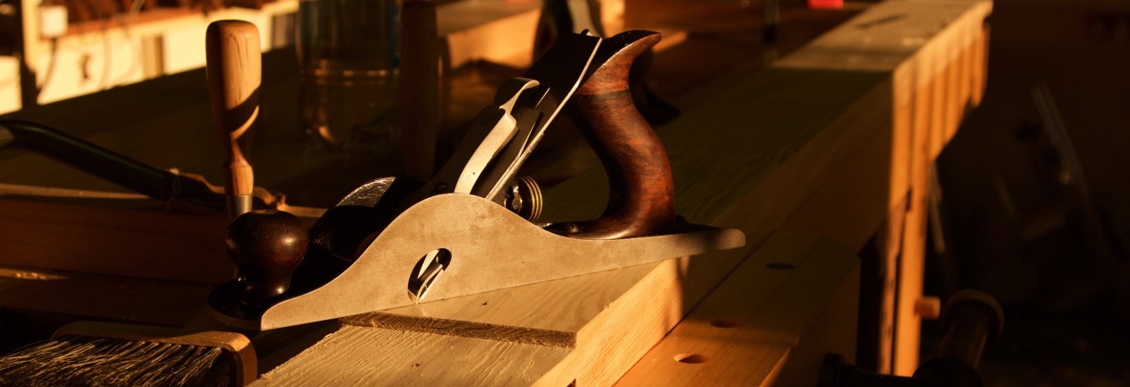
I used my recently acquired Stanley #10 rabbet plane (ca 1910) to clean up the tenons as the bandsaw is not particularly accurate. You can see how the t-channel stops and dogs work in tandem to speed up work like this on my assembly table.

IMG_2020IMG_2021IMG_2022IMG_2023

At the halve assembled bench I used a chisel and mallet to perfect the shoulders. You can see how the gap between the two parts of the twin-top acts as an ideal clamp gateway.

IMG_2014IMG_2015IMG_2016

I followed the same process as with the tenons of the short stretchers and aprons, in dividing the tenons into three fingers. In this case the outside fingers will extend through the legs to be wedged for more strength.

IMG_2026IMG_2027IMG_2028

Once this was done it was back to the bench to mark out the location of the mortises.

IMG_2029IMG_2030IMG_2031IMG_2032IMG_2033IMG_2034

Here I used my Festool TS55 to cut the end off one part of the top where I need to install the metal quick release end vise.

IMG_2037IMG_2038IMG_2039IMG_2047IMG_2048IMG_2049IMG_2050

At the opposite end of the bench the TS55 helped the start shaping tongue/pins that will fit into the Witpeer breadboard-end. I did the rest with an array of hand tools.

IMG_2040IMG_2041IMG_2042IMG_2043IMG_2051IMG_2052IMG_2070IMG_2072IMG_2071IMG_2073IMG_2074IMG_2075IMG_2077IMG_2078

Here you can get an idea of what the bench will look like eventually.

IMG_2046IMG_2045IMG_2044

I spent lots of time trying to work out exactly where to locate the dog holes in relation to all the other hardware. I decided on 1¾” from the front edge (as per Chris Schwarz advice) and 3″ centre to centre for the line of dogs working in tandem with the end vise. I added a plethora (in other words, most probably a major overkill) of dog holes that could be used with the twin screw vise, as you will see later.

IMG_2024IMG_2025IMG_2036IMG_2035IMG_2053IMG_2054IMG_2055


Seeing that my bench top is a smidgen over 4″ thick, I decided to drill ¾” (deep) x 1″ (diameter) relief holes at the bottom of the top before drilling ¾” (diameter) dog holes from the top down.


IMG_2056IMG_2057IMG_2058

This is a 30 mm (diameter) hole where the 20 mm bolt through the top and apron will be covered with a wooden plug.

IMG_2059IMG_2060IMG_2061

I used this crappy Chinese contraption to drill the dog holes as close to 90° as possible. The last picture show the Witpeer breadboard-end on which I stood in order to drill the dog holes.

IMG_2079IMG_2080IMG_2081IMG_2082IMG_2083

At this stage my plan is to make two planing stops that will fit through holes shaped as pictured below.

IMG_2084IMG_2085

Marking out the long stretchers’ mortises.

IMG_2062IMG_2063IMG_2064

In order to get the optimum dog hole layout and for it not to interfere with twin screw vise hardware I had to shorten the chain of the Lie-Nielsen vise ever so slightly. In the process I lost about 1″ capacity between the two vise screws. It went from 24″ to 23″.

IMG_2065IMG_2066IMG_0153IMG_0155IMG_0156IMG_2067IMG_2068

At this stage I took the three beech boards which were acclimatizing in the shop roof down to process them into a leg vise chop, twin screw vise chop and a cover for the inside face of the quick release vise.

IMG_2069

My 18th Century Workbench in progress 16

10/8/2014

I am very happy to report that I managed to fit two legs to the one part of the twin-top this weekend. The first was quite a mission, but the second not so much. One really needs a healthy dose of patience for this work and it does not help much that I am starting to feel pressured to get the bench assembled before the changes in ambient humidity (probably some time in November).

IMG_1981IMG_1982IMG_1983IMG_1984IMG_1985IMG_1986IMG_1987IMG_1988IMG_1989IMG_1990IMG_1991

The second leg. You might notice the gaps on either side of the through tenon’s mortise that was created to accept wedges.

IMG_1992IMG_1993IMG_1994IMG_1995IMG_1996

I inserted the apron and took these photos to give you an idea of the base structure of the bench.

IMG_1997IMG_1998IMG_1999

A week ago I started to take the Irwin quick release vise (destined to become the end vise) apart in order to “paint it black”, as I am a Stones man.

IMG_1939IMG_1940IMG_1941IMG_1942IMG_1943IMG_1944IMG_1945

My 18th Century Workbench in progress 15

3/8/2014

I started cutting the tongue and groove joints on these Kaapse Swarthout boards destined to become the shelve below the twin-top using my Lie-Nielsen tongue and groove plane. The first task however was to arrange the boards so that the edges would fit best in terms of colour and grain pattern. Once I felt please with the arrangement I marked the order using a carpenters triangle.

IMG_1785IMG_1786IMG_1787IMG_1788IMG_1789IMG_1791

Once I started cutting the joinery, I realised that the boards were obviously thicker than ¾” (the thickness where this no. 48 plane centers on) which meant that another “tongue were left on the male edge of the joint. After taking one shaving I first drew a picture on a piece of paper (pictured) to work out how to fix this problem and realised that I simply had the remove the extra tongue with my #78 rabbet plane and all should be sweet.

IMG_1794

As you can see here.

IMG_1796IMG_1797IMG_1798

While all this were going on I liberated the Lie-Nielsen vise hardware from the safety of it’s packaging. Here you can see what it looks like.

IMG_1851IMG_1852IMG_1853IMG_1854IMG_1855

On Saturday I started my next onslaught on the female parts of the leg-to-top joinery.

IMG_1916IMG_1917IMG_1923IMG_1924IMG_1925IMG_1926IMG_1930IMG_1931

Luckily I had another look in Chris Schwarz’s book on building benches and saw that he actually make reference to the fact that one needs to remove the blade adjuster from our router plane to reach this depth. It meant that I could use this very useful tool to clean out the majority of the through dovetail dado (for lack of a better term), before using that flat surface as a reference to guide my chisel while removing the rest by horizontal pairing.

IMG_1927IMG_1929IMG_1946IMG_1947

Here are two closeups of the router plane with the depth stop and blade adjuster removed.

IMG_1948IMG_1949

I then took to the long stretchers with my shop made scrub plane to remove the excess timber from the strips I laminated on last week.

IMG_1918IMG_1919IMG_1920IMG_1921IMG_1922


My 18th Century Workbench in progress 14

21/7/2014

This weekend I started doing further work on the long stretchers, which included final hand planing of the swarthout cleats you’ve met before. In the pictures below you can see how my shop made winding sticks came in handy.

IMG_1749IMG_1750IMG_1751IMG_1753


Between working on the stretchers I got so tired of drilling out waste with the brace and bit that I decided to giving the electric drill a go using a spade bit. I first set the drill to it’s slowest (and therefore strongest) speed and realised that it actually made short work of the waste removal. The drill did not even heat up at all, but never the less I did the drilling in many short bursts between other work. Of coarse the downside was that I realised how much religious baggage I still carry, as a peculiar guilt fell over me when the electric drill completed the job I started with the brace and bit.  Luckily it did not manage to get much of a hold on me before moving on to other hand tool work.


IMG_1754


My shop made panel gauge again came in handy to mark out the area on the inside of the long stretchers where I had to remove some Witpeer to accommodate the cleat. I removed the bulk of it with my Festool router and tidied up the mess left with a Stanley no 78 rabbet plane and my shop made shoulder plane. These tools leave a much better finish and enables you to dial in slowly to the absolute exact size of the rabbit needed.


IMG_1755IMG_1756IMG_1757IMG_1758IMG_1759IMG_1760IMG_1761IMG_1762IMG_1763IMG_1764IMG_1765IMG_1765


The next rabbit is meant to accept the endgrain of Kaapse Swarthout boards sitting diagonally on top of the cleat to form the shelve. I used the same sequence of tools used.


IMG_1766IMG_1767

IMG_1768


While all this was going on I set up the second part of the twin-top in order to saw and chisel out the sliding dovetail dados. You will notice that I used the cleats temporarily as braces for the Darwinian saw horse as they were a bit wobbly when I did the same to the other part of the twin top. It made a massive difference.

IMG_1769IMG_1770IMG_1771IMG_1777IMG_1778IMG_1779

Once again the Festool Domino enabled me to line the additional strip of Witpeer up perfectly with during the lamination process. As per usual, I used the Proletarian sanding contrivances to get rid of machine marks on the glue surfaces.

IMG_1780IMG_1781IMG_1782IMG_1783IMG_1784


My 18th Century Workbench in progress 13

14/7/2014

This weekend I finally managed to do the last massaging work needed to fit the short aprons and stretchers to their respective legs. You can see how well it all came together. Thank you David Charlesworth for all the tips in those DVDs that made it possible for a novice to get it done like this. As you can see I added quite a few layers of leather to one face of my heavy dead blow mallet during the previous week in order not to damage the work while tapping these gargantuan tenons home. Once assembled I positioned the legs on the two parts of the twin-top for marking out the through tenons and sliding dovetails.

IMG_1671IMG_1672IMG_1673IMG_1674IMG_1675IMG_1676IMG_1677

I consulted the installation instructions of the Lie-Nielsen twin screw vise to make sure that the position of the legs does not interfere the positioning of the vise. Of coarse I did not keep track of the fact that the table was now upside down and that I needed to consider this when placing the legs and twin screw vise. After I did all the careful marking out and stood back, it dawned upon me that my twin screw face vise would end up on the right hand side of the bench once it is flip over onto it’s legs. Bugger!! So I had to start all over, but still prefer this to not realising and stuffing up the bench completely.

IMG_1678IMG_1679IMG_1680IMG_1681IMG_1682IMG_1683

Once the various areas were marked out for the second time, I carefully transferred it to the opposite side and clearly indicated the waste to be removed.

IMG_1684IMG_1685IMG_1686IMG_1687

In order to have a slightly more stable top beam to work on I clamped the two part of the top (first picture) together with two pipe clamps. Then I used my Lie-Nielsen tenon saw to cut the sides of the sliding dovetail dado (not sure if this is the correct terminology, but I am sure the pictures will make it clear). The pictures show the sequence of cuts I made in the waste area.

IMG_1690IMG_1691IMG_1692IMG_1693IMG_1694IMG_1695IMG_1696IMG_1697IMG_1698

The chisel did the rest as you can see.

IMG_1702IMG_1703IMG_1704IMG_1705IMG_1706IMG_1707

I thought I could use my Lie-Nielsen router plane to clean out the bottom of the sliding dovetail dados but it did not have the required reach.

IMG_1708

Drilling out the waste from the mortises had to be done by hand as a 1″ drill in a handheld drill would surely destroy the motor in no time. This was thus the first job ever for my new purchased no 923 10″ Stanley brace. It is such hard going that I had to engage the ratchet mechanism to allow me to pull only, rather than trying to go through the full 360º, which is simply beyond my strength.

IMG_1709IMG_1710IMG_1711IMG_1712IMG_1719IMG_1724IMG_1726IMG_1731


My 18th Century Workbench in progress 12

28/6/2014

I went through the same motions with the other side of the top. You can see in some of the pictures what beautiful full length shavings I produced with my shop made jointer.

IMG_1419IMG_1420IMG_1421IMG_1422IMG_1423IMG_1418IMG_1440IMG_1441

In order to remove the bulk of the material on the opposite edge, I first used my shop made scrub plane as a very aggressive fore plane (with the grain). You can see the shavings produced by the heavily cambered blade (3″ radius), measured 0.35 mm (0.014″) in thickness. It made short work of the waste that needed to be removed.

IMG_1442IMG_1443IMG_1458IMG_1459IMG_1460IMG_1462IMG_1463IMG_1464

Again, just some evidence of all the heavy hand planing that I have been engaged in for the past few weeks.

IMG_1468IMG_1469IMG_1470

I finally returned to the mortises and tenons of the aprons and stretchers. It all needed some TLC to fit together perfectly. I used a float and a few chisels to do the fine tuning. I have to say that for a first attempt at such massive joints it all came together splendidly. You will notice the gaps at the top and bottom of the through tenon/mortise created to except wedges.

IMG_1474IMG_1475IMG_1476IMG_1471IMG_1472IMG_1473IMG_1477IMG_1478IMG_1479IMG_1480IMG_1481IMG_1482IMG_1483IMG_1484IMG_1487IMG_1488IMG_1489IMG_1490IMG_1491IMG_1492


My 18th Century Workbench in progress 11

16/6/2014

At this point in time I took a break from all the mortising, to build a monster Panel Gauge. Look out for a post entitled “Makeshift Panel Gauge”, which is soon to be released. I need one for the next major hand planing war that is about to break out in the previously peaceful surroundings of my workshop. I need to flatten the edges of the two parts of the twin-top. They are too big to fit through my planer, so after flattening one edge I will need to use a panel gauge to mark out the opposing side and hand plane that parallel to the reference edge. The mortises below are only one step away from being finished.

IMG_1180IMG_1181IMG_1182IMG_1183


23/6/2014

In the meantime I realised that I need to start squaring up the two beams of the twin top. As they are too wide to fit in my planer upright I will have to do that (planing to width) by hand planing. Once I get one edge square to the face side I will need a panel gauge to mark out the opposite side. Problem is, I do not have a panel gauge of that size. The idea was to build a makeshift panel gauge as I wanted to get onto the next step with the bench, but my tool design-OCD kicked in and it led to a protracted design and manufacturing hiatus. The end product is featured in the pictures below. I wrote a post on the process entitled “Makeshift Panel Gauge”.

IMG_1360IMG_1362

This past weekend the process of hand planing these monster beams started with a vengeance. I like starting off by hollowing out the face side ever so slightly. I used the short straight edge to check all along the length of the face side. If it does not pivot on the edges, it is not hollow yet.

IMG_1370IMG_1386IMG_1389IMG_1387IMG_1388


Next I check for wind using my truly makeshift winding sticks. This is why I start by hollowing out the face side from side to side, otherwise you get the wrong reading when using the winding sticks. If there is a bump at any point across the width, the winding stick can adopt one of two different positions. Once the winding sticks make contact with the face side’s edges only you get the true reading and can therefore proceed to fix the twist. In this case I had minimal work to do as I removed (by hand planing) most of the twist prior to feeding the beams to my planer about 6 weeks ago.

IMG_1371IMG_1372


Once the face side was slightly hollow and twist free, I could square the face edge using the face side as reference. You can see how my shop made jointer came in very handy.

IMG_1373


Then I used my newly produced panel gauge to mark out the opposite edge to be parallel to the reference edge.

IMG_1375IMG_1378IMG_1377IMG_1380IMG_1391IMG_1392IMG_1411


My 18th Century Workbench in progress 10

2/6/2014

Once again I took the measuring out quite serious spending most of a Saturday morning to measure out exactly were the mortises should be cut in the legs. I made the effort to measure the shoulder of each specific tenon at the top and bottom (of the in and outside) with the Veritas marking gauge (pictured) and transferring that to the leg to ensure that I get as close as possible to perfect. The four reference points generated in this way were then used to cut the long sides of the rectangle by means of a marking knife and straight edge. The short sides were cut using a square guided by the pencil marks of the actual tenons on the leg as demonstrated in the previous set of photographs. You will notice that each mortise have a entrance side and a exit side.

IMG_1035IMG_1043IMG_1044IMG_1046IMG_1036IMG_1038IMG_1039IMG_1040IMG_1041IMG_1042

Since I recently realised how useful dividers can be in marking and laying out all sorts of measurements in woodwork, I used it to establish which size drill bits would work best for the removal of the waste from these mortise. It also came in very handy in marking out where to drill the holes. You will notice how I marked out the location of each assault on the mortise, as well as writing the diameter (in millimeters) of the spade/Forstner bit to be used in pencil.

IMG_1047IMG_1048IMG_1050IMG_1049IMG_1051IMG_1052IMG_1053IMG_1054

All the tenons will be pinned in two places. Here you can see how I marked out where to drill the holes for the 10 mm custom made Assegaai dowels. These dowels are still to be made. Please note that the holes for the long and short stretchers will be in the same plane, which is contrary to what is usually done. I decided to break this very sensible rule as the design of my tenons (for reasons of wood movement) does not allow enough room to have them in different planes while still being imbedded in a robust hunk of timber. You will see how I plan to overcome this particular challenge as we progress.

IMG_1045IMG_1046

IMG_1055IMG_1056IMG_1057IMG_1058IMG_1059IMG_1060


Here I started removing the bulk of the waste from the mortises on the drill press. It looks like a piece of pie, but it took ages, trust me.

IMG_1061IMG_1062IMG_1063IMG_1064IMG_1065IMG_1066IMG_1067IMG_1068

IMG_1069IMG_1070IMG_1117IMG_1118IMG_1119IMG_1120


Then came the real elbow grease part of the job, removing the rest by means of a mortise chisel and a shop made mallet. Whack, whack, whack, whack, whack, whack, whack, whack, whack, whack, ……………………………………. (weeks later)………………………… whack, whack,whack,whack ………………….. (even more weeks later) …………. whack …… OK I am sure you get the picture.


IMG_1121IMG_1123IMG_1124IMG_1125IMG_1132IMG_1133

IMG_1134IMG_1135IMG_1136IMG_1137IMG_1138IMG_1139IMG_1140IMG_1141IMG_1142


Some evidence that I really did do all that drilling and especially all that whacking.

IMG_1143IMG_1145IMG_1146


While all the whacking was going on I milled down the swarthout (which was laminated six weeks ago or so) destined for the cleat under the shelve between the stretchers, in order to take a well deserved break.

IMG_1161IMG_1162IMG_1163


….. and whack whack whack etc etc ……

IMG_1164IMG_1165IMG_1178IMG_1179


My 18th Century Workbench in progress 9

25/5/2014

I managed to chip away at preparing the aprons a little bit each night during the week. Here you can see how I squared up the shoulders first by chopping down using the prop to improve accuracy and finally some horizontal pairing to get it perfect.

IMG_0934IMG_0935IMG_0936IMG_0937IMG_0939IMG_0940IMG_0941IMG_0942

Then I moved on to a plan I dreamt up to deal with wood movement. Windhoek has some of the most challenging seasonal changes in humidity of any location in this part of the world. In my shop the ambient humidity changed from 20-25% in winter to 75-80% during the rainy season last year. This means that the Equilibrium Moisture Content of the wood (which average around 6%) can fluctuate between 1-11%. This represents a major challenge when building a bench that needs to stay as flat as possible. This is the main reason why I designed my bench with a split top to allow the two parts (which will be fixed to the legs by means of the Roubo through tenon and sliding dovetail joints) to move into the space between them, rather than trying to pull the leg-apron joints apart. Please note the elongated hole for the 20 mm threaded rod that will fix the top to the apron, which is meant to allow for the mentioned horizontal wood movement.

In order to deal with the vertical movement of the top, I use the following strategies: 1) chose quarter sawn stock for the aprons, 2) cut relief gaps (for a lack of a better term) into the aprons. The holes drilled into the aprons in the pictures below, was the start of that process. Hopefully the pictures will do a better job of explaining.

IMG_0943IMG_0944IMG_0945IMG_0946IMG_0947IMG_0948IMG_0949IMG_0951IMG_0953IMG_0954IMG_0955IMG_0956IMG_0958IMG_0959IMG_0960IMG_0961IMG_0962IMG_0964


Here I did a quick check to make sure the 20 mm threaded rod is able to move freely in the elongated slot.

IMG_0965IMG_0966

I then grabbed the router to remove an area to allow the bolt to be countersunk below the bottom surface of the apron. This is important to ensure that a clamp can still find a nice flat surface in future, then using F-style clamps through the split top.

IMG_0967IMG_0968IMG_0969IMG_0970IMG_0971IMG_0972IMG_0973IMG_0974

The router also assisted with the initial 20 mm (depth) or so, of this 6 mm (width) relieve groove, before I took to it with the drill press, a chisel and finally a bed float.

IMG_0975IMG_0976IMG_0977IMG_0978IMG_0979IMG_0980IMG_0981IMG_0982IMG_0983IMG_0986IMG_1002IMG_1003IMG_1004


I used the bandsaw to cut two 3 mm wide relieve grooves in each tenon which extends and overlaps with the aforementioned relieve groove. This will hopefully mean that the tenon (which is about 115 mm (about 4½”) wide) will be able to expand without destructing the joint and for the apron to have minimal effect on the top when it inevitably moves throughout the year.

IMG_0987IMG_0988IMG_0989IMG_0990


The three ‘fingers of each tenon were then cut to length. You will notice that there are a short haunch at the top (which stops short of the main tenon at the top of the leg in order not to weaken it) a through tenon in the middle (which will be wedged at the front of the leg) and a normal tenon at the bottom (which stops about 1″ short of the front of the leg). Both middle and bottom tenons will be pinned with a custom made 10 mm Assegaai dowel.

IMG_0991IMG_0992IMG_0993


Then I turned my attention to the end (short) stretchers. I followed the same process as with the aprons. I only difference was that I found it a bit tough going with the carcass saw cutting the shoulders so I tried the tenon saw and it worked like a charm. The teeth of the tenon saw are set for ripping but I can honestly say that it worked as well as the carcass saw, only better because of the bigger teeth and extra weight and length it brought to the party.

IMG_0994IMG_0995IMG_0996IMG_0997


The waste was removed by chisel.

IMG_0998IMG_0999IMG_1000IMG_1001IMG_1005IMG_1006

The shoulders were squared up by chopping followed by horisontal pairing.

IMG_1008IMG_1009IMG_1010


Seeing that it is insignificant whether the stretchers move slightly, I only cut the relieve grooves in the tenons to protect the integrity of the join.

IMG_1012IMG_1011IMG_1013IMG_1014IMG_1016


As with the aprons the three fingers of each tenon were cut to different lengths. In this case the two outside tenons were shortened and the one in the centre were left long to become a through tenon to be wedged. Both the outside tenons will be pinned too. I plan to do the opposite with the side stretchers where the outside fingers will be through tenons and the central one shortened.

IMG_1017IMG_1018


On to the female parts of these joints. I used the same setup as before to mark out exactly where to cut the mortises using the actual aprons and stretchers. Again the position of the legs were referenced off the inside shoulders of the through tenon at the top of the legs (see first picture).

IMG_1019IMG_1020IMG_1021IMG_1022IMG_1023IMG_1024IMG_1025IMG_1026IMG_1027IMG_1028IMG_1029IMG_1031IMG_1032


My 18th Century Workbench in progress 8

30/4/2014

Attila Hoth dropped off the three beech boards I requested tonight. As we are about to abandon Windhoek for a 10 day migration to our Fishing Camp on the mighty Okavango River for a spot of Tiger fishing, I simply clamped them to my assembly table to stay honest while settling into my shop’s particular ambiance.

Tweede hout

18/5/2014

Finally I was able to progress with the joinery this weekend after our African adventure. First on the to-do list was to use the actual leg to mark out the shoulder lines of the short stretchers and two aprons. The work-holding ability of my shop made assembly table made it possible to set up a frame in order to mark out each set exactly the same. You will notice that I referenced the vertical position of the legs off the shoulders of the through mortises. For the width of the bench I finally settled on a fraction over 25″.

IMG_0875IMG_0876IMG_0877IMG_0878IMG_0879IMG_0881IMG_0882IMG_0883

In order to locate the short stretchers, I made two batons of 3 mm plywood that are exactly the same length and used that to reference off the bottom of aprons, which were in turn set up flush with the tenon shoulders. With all the parts firmly clamped into position as you can see in the last picture, I used a 0.3 mm mechanical pencil to mark out the exact shoulder lines on the apron and stretcher. Then it was simply a question of repeating the process on the second set of parts.

IMG_0884IMG_0885IMG_0886IMG_0887IMG_0888IMG_0889

The pencil lines generated during the above activity was then used to mark out the rest of the shoulder lines with a marking knife, while taking care to always reference off a face side or face edge. You will see that I have started using the technique/scribble taught by Robert Wearing to indicate the two face sides.

IMG_0890IMG_0891IMG_0892IMG_0894

At this point I realised that I really should add the final part of the stretcher before cutting the shoulders. I decided a while ago already to laminate yet another strip to make it appear as if the stretcher is solid Witpeer. Therefore I had to mill another feral board into sophisticated strips for the top of all four stretchers and laminated it onto the already ominous looking (3″ x 5½ before the strips were added) short stretchers.

IMG_0895IMG_0896IMG_0897IMG_0898IMG_0902IMG_0914IMG_0915

In the meantime I started sawing the shoulders of the aprons and made a point of trying to saw to the line. I did not want to remove as much material with the chisel as what I had to do on the through mortises at the top of the legs. Again I used one of Robert Wearings tricks to get the saw started perfectly. He describes how you used a chisel to pair a shallow ditch (pictured) on the waste side of the shoulder line to guide you saw. Once the shoulders were cut it was piece of pie to chop the waste away with a chisel.

IMG_0899IMG_0900IMG_0901

The big frustration of the weekend was when I realised that I still needed to cobble together a fence for the #78 Stanley rabbet plane (that I am in the process of restoring into a working tool) before I can use it to hand-cut mouldings with it. That forced me to design and fashion this Ferrari-esque contrivance …

IMG_0919IMG_0920

… which despite it’s dilapidated appearance, performed admirably in tandem with a small block plane and a card scraper in producing these hand-cut mouldings . You will notice that these mouldings were designed to hide the lamination. Together with a good colour match it makes it impossible to notice the lamination, once the stretcher’s shoulders are glued into position between the legs.

IMG_0921IMG_0922IMG_0923IMG_0924IMG_0925IMG_0926IMG_0927IMG_0928IMG_0929IMG_0930IMG_0931IMG_0932IMG_0933


However, that took most of the day so I ended up feeling a bit despondent about the weekends progress.