All posts by Gerhard Marx

Psychiatrist and Woodworker

My 18th Century Workbench in progress 21

6/10/2014

I really do hope that this will be the last post that does not include a picture of the assembled bench. I am starting to get a bit worried that I might not be able to get it assembled before the major changes in humidity. To give you an idea, the ambient humidity in my shop change from around 25-30% in winter to 75-80% during the rainy season.

Here you can see how I fitted the legvise hardware to the leg that will play host to the mentioned vise.

IMG_2237IMG_2260IMG_2261IMG_2262IMG_2263IMG_2264IMG_2267IMG_2265IMG_2266

The next task was to do some of the preparation work to eventually fit the breadboard-end. The rest of this process can only be done once the bench is assembled for the (hopefully) final dry run.

IMG_2259IMG_2251IMG_2252IMG_2253IMG_2254IMG_2255IMG_2256IMG_2257IMG_2258

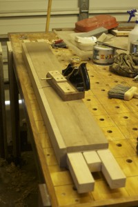
This piece of Ysterhout was processed as pictured to become the planing stops. You can also see how I marked out and chopped the holes in the top to accommodate them. My cousin, a Urologist from Cape Town, did the final tidying up of the two orifices. He seems to have a particular talent when it comes to an orifice.

IMG_2155IMG_2273IMG_2274IMG_2275IMG_2276IMG_2277IMG_2278IMG_2279IMG_2280IMG_2281IMG_2282IMG_2283IMG_2287IMG_2288

While he was perambulating the two orifices, I started fitting the long stretchers to their legs.

IMG_2295IMG_2296IMG_2297IMG_2298IMG_2299IMG_2304IMG_2305

Here I just finished excavations for the end vise to be fitted.

IMG_2300IMG_2301IMG_2302IMG_2306IMG_2307

Shop made Ysterhout straight edge

16/9/2014

I have been looking for a suitable piece of timber to use as a straight edge for a while now. A few weeks ago I found this piece of Ysterhout that has been kicking around the shop for the past three years. I did not even consider Ysterhout as an option as it is not particularly stable in my experience. When I picked up this piece while ferreting around for a suitable piece of Witpeer, I saw that it was dead straight with grain to match. It is the piece on the right in the picture below.

IMG_2176

I planed it down to a thickness of a ½” over the coarse of several days and it stayed dead straight. The design I chose has the specific purpose of exposing as much end grain as possible in an attempt to help the timber to adjust to changes in ambient humidity in no time.

IMG_2186

After shaping it as pictured, I left the straight edge for a few days before fine tuning the business end.

IMG_2268IMG_2269

A coat of Tung oil finished the job.

IMG_2270IMG_2271IMG_2272

My 18th Century Workbench in progress 20

15/9/2014

I started off the weekend by using my no 78 Stanley rabbet plane with it’s sexy (yeah right) shop made fence to shape the moulding at the top of the long stretchers. The moulding has three primary functions. It aims to hide the fact that it is a laminated beam of Witpeer. You will find that the two small steps are placed to hide the lamination line on the side of the stretcher.

IMG_2207IMG_2208IMG_2174IMG_2175IMG_2211IMG_2212

The chamfer I am working on here creates a v-shaped surface for the foot of the sliding deadman to slide on and hopefully adds some aesthetic value too.

IMG_2187IMG_2188IMG_2189IMG_2190IMG_2191IMG_2198IMG_2199

Here you can see the array of planes used the create the moulding.

IMG_2235IMG_2203IMG_2201IMG_2200IMG_2202

I then moved on to seating the twin screw vise stand offs. The 30 mm diameter holes meant to accept the ACME threaded rod were already drilled through the top a week or so ago. I used an electric hand drill with a spade bit to remove the bulk of the waste before chopping the rest out with my Lie-Nielsen ½” mortise chisel.

IMG_2182IMG_2183IMG_2185IMG_2193IMG_2192IMG_2194IMG_2197IMG_2205IMG_2206

That got me this far.

IMG_2210IMG_2209

The electric router removed most of the waste for the shoulders (so to speak) of the stand offs. I then used the router plane pictured to dial it in to the exact depth.

IMG_2213IMG_2214IMG_2215IMG_2218IMG_2217IMG_2222


IMG_2221IMG_2226

The result.

IMG_2223IMG_2225IMG_2227


Next I marked out and drilled the holdfast holes in the legs on the drill press. You will notice that the ¾” holes are relieved to 1″ from the back of the leg.

IMG_2229IMG_2230IMG_2231IMG_2232

IMG_2233

Replacing Lie-Nielsen mortise chisel handle

8/9/2014

A few weeks ago the original Hornbeam handle of my ½” Lie-Nielsen mortise chisel expired as pictured. Being smashed constantly with a shop made Ysterhout mallet does not seem to agree with Hornbeam’s constitution. Ysterhout (Olea capensis macrocarpa) at a Janka side hardness of 10,050–13,750 N and Janka end hardness of 9780–14,200 N makes Hornbeam feel like a marshmallow. It thus made sense to turn the new handle out of Ysterhout, which I duly did.

I quote from a bit of interesting info on this species for you from the website indicated below.

Uses and cultural aspects
An authoritative source (Mabberley, 2008) informs us that ironwoods have the heaviest known timber, with a recorded specific gravity of 1.49. In other words, the timber of these trees sinks like a stone when put into water. Ironwood timber has long been respected, but its weight and hardness have to some extent limited its popularity, and it is not as widely encountered in antique furniture as, say, stinkwood, yellowwood or Indian teak. However, Hartwig (1973) reports the existence of antique ploughs and harrows made at least partly of ironwood. The limited use implied by Hartwig fits well with Von Breitenbach’s (1974) observation that the early foresters left a disproportionate number of large black ironwood trees standing, because with only hand-powered tools, it was much more profitable to go after yellowwood and stinkwood – for the effort involved in felling and removing one ironwood, they could process several of the other trees. Nonetheless, Von Breitenbach reports that the wood is suitable for sleepers, piles, flooring and veneers. One can imagine that the objection to making furniture out of the solid wood is that the results would be so heavy as to be almost immovable. The use of these trees for firewood, and (while living) for shelterbelts and as ornamentals is recorded.

http://www.plantzafrica.com/plantnop/oleacapensis.htm

IMG_2180IMG_2181


I though I would turn two while I am at it.

IMG_2156IMG_2167

Straight after being seated.

IMG_2168IMG_2169


15/9/2014

After a bit of pounding.

IMG_2177IMG_2178IMG_2179


My 18th Century Workbench in progress 19

8/9/2014

At this stage it was back to the drill press to remove some waste from the mortises before butchering the rest away by means of a mortise chisel and mallet madness.

IMG_2086IMG_2087IMG_2088

I used my Festool router to cut the dado in which the top of the deadman will slide. The same router were then employed to cut the dadoes in which the tool trays will slide between the two parts of the twin-top.

IMG_2109IMG_2110IMG_2111IMG_2112IMG_2113IMG_2114IMG_2115IMG_2117IMG_2116IMG_2118IMG_2120IMG_2121IMG_2122IMG_2123

As per usual I flattened one side of the beech boards destined to become the twin screw vise chop with hand planes, removed the twist and finished the job off with the planer. They were then clamped to the assembly table and left to settle for a few days while I continue with other bits and pieces.

IMG_2124IMG_2125IMG_2133IMG_2134

One such task is painting the Irwin quick release vise black as it’s traditional blue does not fit into my idea of je ne sais quoi.

IMG_2131IMG_2132

Shop made pairing handle for my Lie-Nielsen bevel edge chisels

8/9/2014

This past weekend I had to replace the chopping handle of my Lie-Nielsen mortise chisel, as the Hornbeam original succumbed to hours of relentless pounding with my Ysterhout mallet. While I was doing this I thought it would be a good idea to also turn a longer Ysterhout handle for pairing purposes. You can see what it looks like in the pictures below. I can now use it on all my Lie-Nielsen bevel edge chisels to convert them into pairing chisels in no time.

IMG_2170IMG_2171IMG_2172IMG_2173

My 18th Century Workbench in progress 18

27/8/2014

Last night I sat down to design the chop of the leg vise. I wanted to come up with something fresh that I have not seen before, yet without compromising on the function of the chop. The pictures below show my freehand concept sketches. You will have to wait until we build the chop to see how we create this appearance. I still do not know myself, but time will tell. I will add the photos of how the chop develops to this post as it happens.

IMG_0159IMG_0160


8/9/2014

Here you can see how I processed some beech using my band saw and planer. I am aiming for a chop that is about 2″ thick after laminating these strips.

IMG_2089IMG_2090IMG_2091IMG_2092IMG_2093IMG_2094

In order to lose as little thickness as possible I hand planed one edge of each strip flat and used that as a reference surface to guide my Festool Domino. The dominos help to keep the reference edges flush during the glue-up.

IMG_2095IMG_2096IMG_2097

I arranged the strips as pictured with attention to it’s end grain.

IMG_2098IMG_2099


In these pictures you can see how my assembly table and a few clamps assisted to hold the strips while cutting the domino slots.

IMG_2100IMG_2101IMG_2102IMG_2103


My skill to and method of lamination has improved significantly as a result of the shear volume of lamination required during this project. I use my shop made proletarian sanding contrivances loaded with a range of different grit sandpaper (120, 150, and finally 240) to remove machine marks from the glue surfaces.

IMG_2105IMG_2107IMG_2106IMG_2104IMG_2108IMG_2126IMG_2128


After flattening one face of the laminated stock with a range of hand planes it was used as a reference surface in the planer to flatten the opposite face. I then marked out the curves, drilled the holes for the vise screw etc etc.

IMG_2135IMG_2136IMG_2137IMG_2139IMG_2140IMG_2138IMG_2141


Here I removed the bandsaw ripples with my Lie-Nielsen block plane followed by some attention from the proletarian sanding contrivances (aka sanding planes).

IMG_2142IMG_2143IMG_2144


Then I started shaping the chop as pictured using my late 19th century Buck Bros. drawknife followed by a series of rasps and files.

IMG_2145IMG_2146IMG_2147IMG_2148IMG_2149IMG_2150IMG_2151IMG_2152IMG_2153IMG_2154


6/10/2014

IMG_2291IMG_2292IMG_2293IMG_2294IMG_2349


3/11/2014

A quick dry fit with the bench assembled.

IMG_2574IMG_2575IMG_2576

Here I prepared the tenon for its two wedges.

IMG_2579

I shaped the top of the jaw at an angle. I thought I would first use the vise for a while, before trimming it flush to the top of the bench. That way it has some time to settle.

IMG_2580IMG_2581IMG_2582IMG_2583IMG_2584

The toe was shaped as pictured.

IMG_2588IMG_2589

I chose Namibian Skeleton Coast seal bull leather to add grip to my leg vise. It is incredibly tough stuff.

IMG_2585IMG_2586IMG_2590IMG_2591IMG_2592IMG_2593

This is officially my first attempt at carving.

IMG_2594IMG_2595

The chop was glued into position using the pictured method to ensure that it is lined up absolutely spot on.

IMG_2600IMG_2601IMG_2602IMG_2603IMG_2604IMG_2605IMG_2606IMG_2607

Now this next process took some time to find a solution for. I decided to add leather to the leg as well, but wanted it to remain flush with the rest of the front of the bench. Therefore I needed to remove wood (about ¾ of the thickness of the leather) in the area where the vise jaw touch the bench and leg. It was quite a mission, but I finally managed to do it with the help of my router plane.

IMG_2596IMG_2597IMG_2608IMG_2609IMG_2610IMG_2611IMG_2612IMG_2613IMG_2614


This way the leather becomes flush with the front of the bench once some pressure is applied by the jaw. So far so good.

IMG_2627IMG_2632


My 18th Century Workbench in progress 17

24/8/2014

It was with more than a wee bit of apprehension that I partly assembled the bench for the first time. The reason being that I had to mark out the exact location of the shoulders of the long stretchers. The good news is it went together like a dream. The 18th century exposed joinery is bombproof, even without glue, draw pins and wedges. Once those are added it would be impossible to destroy during normal shop work. Here you can see how I clamped the long stretcher in position using two batons of equal length referencing off the underside of the top.

IMG_2000IMG_2001IMG_2003IMG_2004IMG_2005IMG_2006

While the bench was semi assembled I used the opportunity to mark the location of the hole that will accept the 20 mm bolt to fix the top to the apron. I used my shop made Witels marking knife with it’s extra long blade.

IMG_2007IMG_2008

I then used my tenon saw (as my carcass saw is simply too small) to cut the long stretcher’s tenon shoulders. The rip cuts were done on the bandsaw, because it was significantly beyond the capacity of my tenon saw.

IMG_2009IMG_2010IMG_2011IMG_2012IMG_2013

I used my recently acquired Stanley #10 rabbet plane (ca 1910) to clean up the tenons as the bandsaw is not particularly accurate. You can see how the t-channel stops and dogs work in tandem to speed up work like this on my assembly table.

IMG_2020IMG_2021IMG_2022IMG_2023

At the halve assembled bench I used a chisel and mallet to perfect the shoulders. You can see how the gap between the two parts of the twin-top acts as an ideal clamp gateway.

IMG_2014IMG_2015IMG_2016

I followed the same process as with the tenons of the short stretchers and aprons, in dividing the tenons into three fingers. In this case the outside fingers will extend through the legs to be wedged for more strength.

IMG_2026IMG_2027IMG_2028

Once this was done it was back to the bench to mark out the location of the mortises.

IMG_2029IMG_2030IMG_2031IMG_2032IMG_2033IMG_2034

Here I used my Festool TS55 to cut the end off one part of the top where I need to install the metal quick release end vise.

IMG_2037IMG_2038IMG_2039IMG_2047IMG_2048IMG_2049IMG_2050

At the opposite end of the bench the TS55 helped the start shaping tongue/pins that will fit into the Witpeer breadboard-end. I did the rest with an array of hand tools.

IMG_2040IMG_2041IMG_2042IMG_2043IMG_2051IMG_2052IMG_2070IMG_2072IMG_2071IMG_2073IMG_2074IMG_2075IMG_2077IMG_2078

Here you can get an idea of what the bench will look like eventually.

IMG_2046IMG_2045IMG_2044

I spent lots of time trying to work out exactly where to locate the dog holes in relation to all the other hardware. I decided on 1¾” from the front edge (as per Chris Schwarz advice) and 3″ centre to centre for the line of dogs working in tandem with the end vise. I added a plethora (in other words, most probably a major overkill) of dog holes that could be used with the twin screw vise, as you will see later.

IMG_2024IMG_2025IMG_2036IMG_2035IMG_2053IMG_2054IMG_2055


Seeing that my bench top is a smidgen over 4″ thick, I decided to drill ¾” (deep) x 1″ (diameter) relief holes at the bottom of the top before drilling ¾” (diameter) dog holes from the top down.


IMG_2056IMG_2057IMG_2058

This is a 30 mm (diameter) hole where the 20 mm bolt through the top and apron will be covered with a wooden plug.

IMG_2059IMG_2060IMG_2061

I used this crappy Chinese contraption to drill the dog holes as close to 90° as possible. The last picture show the Witpeer breadboard-end on which I stood in order to drill the dog holes.

IMG_2079IMG_2080IMG_2081IMG_2082IMG_2083

At this stage my plan is to make two planing stops that will fit through holes shaped as pictured below.

IMG_2084IMG_2085

Marking out the long stretchers’ mortises.

IMG_2062IMG_2063IMG_2064

In order to get the optimum dog hole layout and for it not to interfere with twin screw vise hardware I had to shorten the chain of the Lie-Nielsen vise ever so slightly. In the process I lost about 1″ capacity between the two vise screws. It went from 24″ to 23″.

IMG_2065IMG_2066IMG_0153IMG_0155IMG_0156IMG_2067IMG_2068

At this stage I took the three beech boards which were acclimatizing in the shop roof down to process them into a leg vise chop, twin screw vise chop and a cover for the inside face of the quick release vise.

IMG_2069

My 18th Century Workbench in progress 16

10/8/2014

I am very happy to report that I managed to fit two legs to the one part of the twin-top this weekend. The first was quite a mission, but the second not so much. One really needs a healthy dose of patience for this work and it does not help much that I am starting to feel pressured to get the bench assembled before the changes in ambient humidity (probably some time in November).

IMG_1981IMG_1982IMG_1983IMG_1984IMG_1985IMG_1986IMG_1987IMG_1988IMG_1989IMG_1990IMG_1991

The second leg. You might notice the gaps on either side of the through tenon’s mortise that was created to accept wedges.

IMG_1992IMG_1993IMG_1994IMG_1995IMG_1996

I inserted the apron and took these photos to give you an idea of the base structure of the bench.

IMG_1997IMG_1998IMG_1999

A week ago I started to take the Irwin quick release vise (destined to become the end vise) apart in order to “paint it black”, as I am a Stones man.

IMG_1939IMG_1940IMG_1941IMG_1942IMG_1943IMG_1944IMG_1945

My 18th Century Workbench in progress 15

3/8/2014

I started cutting the tongue and groove joints on these Kaapse Swarthout boards destined to become the shelve below the twin-top using my Lie-Nielsen tongue and groove plane. The first task however was to arrange the boards so that the edges would fit best in terms of colour and grain pattern. Once I felt please with the arrangement I marked the order using a carpenters triangle.

IMG_1785IMG_1786IMG_1787IMG_1788IMG_1789IMG_1791

Once I started cutting the joinery, I realised that the boards were obviously thicker than ¾” (the thickness where this no. 48 plane centers on) which meant that another “tongue were left on the male edge of the joint. After taking one shaving I first drew a picture on a piece of paper (pictured) to work out how to fix this problem and realised that I simply had the remove the extra tongue with my #78 rabbet plane and all should be sweet.

IMG_1794

As you can see here.

IMG_1796IMG_1797IMG_1798

While all this were going on I liberated the Lie-Nielsen vise hardware from the safety of it’s packaging. Here you can see what it looks like.

IMG_1851IMG_1852IMG_1853IMG_1854IMG_1855

On Saturday I started my next onslaught on the female parts of the leg-to-top joinery.

IMG_1916IMG_1917IMG_1923IMG_1924IMG_1925IMG_1926IMG_1930IMG_1931

Luckily I had another look in Chris Schwarz’s book on building benches and saw that he actually make reference to the fact that one needs to remove the blade adjuster from our router plane to reach this depth. It meant that I could use this very useful tool to clean out the majority of the through dovetail dado (for lack of a better term), before using that flat surface as a reference to guide my chisel while removing the rest by horizontal pairing.

IMG_1927IMG_1929IMG_1946IMG_1947

Here are two closeups of the router plane with the depth stop and blade adjuster removed.

IMG_1948IMG_1949

I then took to the long stretchers with my shop made scrub plane to remove the excess timber from the strips I laminated on last week.

IMG_1918IMG_1919IMG_1920IMG_1921IMG_1922