All posts by Gerhard Marx

Psychiatrist and Woodworker

Roubo sharpening bench – part 9

7/9/2015

I managed to do a little bit of work during the evenings last week. One of those tasks were to add two strips of Meranti to the sides of the bench top’s centre beam. These strips comes from a doorframe. A friend of mine Anton Nel, rocked up at my shop a few weeks ago with this doorframe. He is a builder and was working on a house just around the corner from us. The so called carpenter on the site, arrived (as is exceedingly common around these parts) without any tools of his own. He needed to remove about 20 mm from each side of the 80 mm thick frame.

My table saw struggled as it is not made for this dimension of cut, so we decided to cut a 20 mm deep groove from both ends as a guide. We then used my monster 26″ Disston no. 12 rip saw to remove the timber between the grooves. Two cuts of 2 meters each had us both sweating like a gypsy with a mortgage.

It was these offcuts that I planed down to 15 mm (thickness), before gluing and screwing it to the sides of the beam. The idea behind the addition of these strips is to close the gap between the three beams that make up the top to only 3 mm. This will be enough to allow for wood movement, but small enough to prevent most things from accidentally falling through.

In the second and third picture below you can also see the slots I made with my Festool Domino. The three beams making up the top will have several dominos between them to help them to keep each other flush and straight. They will not be glued to allow free movement (horizontal), while only restricting movement in one dimension (vertical).

IMG_4983IMG_4985IMG_5016

I used my 10 mm bit to cut the Domino slots. Unfortunately I do not have any 10 mm Dominos so I planed some Witpeer down to the desired dimension. Come to think of it, the standard Dominos would have been too short anyway as these will be breaching an 18 mm gap underneath the Meranti strips, extend 28 mm into one beam and 24 mm into the other. The slots are 28 mm deep in both beams, so the extra 4 mm allows for wood movement. In other words, I need to cut my home made Dominos at 68 mm (in length).

IMG_5017

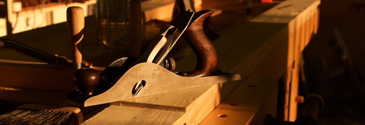
Here you can see how I am progressing with the row of dog/holdfast holes along the front edge of the bench. They are not perfectly in line as the marked difference in hardness between early and late wood cause the auger bit to follow the softer stuff, but I am not overly fussed by this. One could overcome this problem by building a jig, but for this bench it should be fine with the slight meandering of the row.

IMG_4986IMG_4987

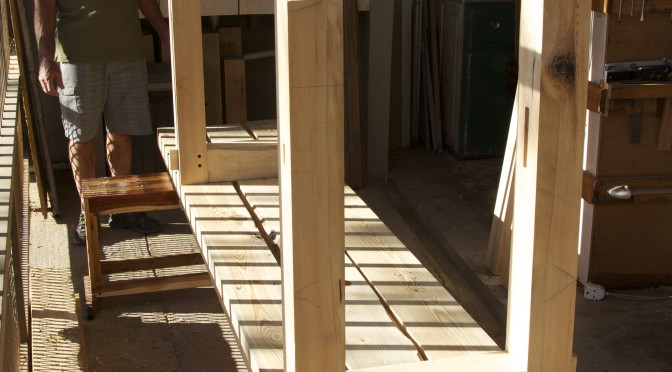
I spent most of my shop time this weekend on fitting the stretchers to their mortices. In the picture below, you can see how my chopping station is on one side of the bench and a station to shave the tenons down on the opposite side. I find it to be a very convenient setup and once again all those dog/holdfast holes come in handy. Monsieur Schwarz might have a heart attack, but he asked to be disobeyed.

IMG_5018

For each leg, I first fitted the long stretcher.

IMG_4989IMG_4990

In this picture you can see how handy the gap between the split top of my bench can be when fitting through tenons.

IMG_5029

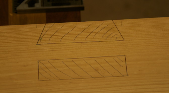
Once the long stretcher’s tenon was in place, I marked out the exact location of the “mortice” that will allow part of the short stretcher’s tenon to run through it.

IMG_4991IMG_5023IMG_5002IMG_5003IMG_5013

Next up, the short stretcher being fitted in the absence of the long stretcher.

IMG_4999IMG_5001

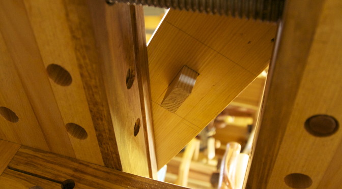
This picture illustrates nicely how the one tenon pass through the other. As I stated in an earlier post, this is a slight variation to the joinery used in my first bench that was inspired by Japanese joinery.

IMG_5000

When fitting massive joints this precise (like a piston, as my friend Jonathan would say), it can be tricky to disassemble them. The picture below illustrate how useful my sliding-deadman-cum-leg-vise proofed to be in this regard. It kept the leg in position at the side of the bench, which allowed me to use both hands to carefully tap the tenon out with a mallet and a small off-cut.

IMG_5024IMG_5025IMG_5026

Once that was done I could check whether both stretchers fit simultaneously.

IMG_5004IMG_5005IMG_5006

At this stage I started to prepare timber for the shelve between the stretchers. I found two Without (Ilex mitis aka Cape Holly/African Holly) boards in my collect that I thought would go very well with the Scots pine (Pinus sylvestris).

Another reason for this choice concerns the fact that I have not worked with this species before. I am consciously trying to use all the different species in my collection during the shop-setup phase of my journey, in order to get a feel for each. Hopefully by the time I start building furniture it will enable me to make smarter choices.

IMG_4994IMG_4995


This is a picture from the internet to show what it looks like once planed and sanded.


cape-holly


The next few pictures should be a reminder to all of you out there who can walk into a lumber yard and pic from hundreds of perfect boards that is ready to use. I have to do a whole heap of work to liberate decent bits of wood from these feral planks. You might be able to see how I marked out the useable areas.

IMG_4996


My Disston no. 12 crosscut handsaw took care of all the crosscuts, while the bandsaw made short work of the rip cuts. I decided to keep the shelve’s boards at different widths to waste as little timber as possible and there seems to be a certain je ne sais quoi about the utilitarian appearance it creates.

IMG_4998IMG_5008


As I said, at least there is minimal wastage this way.

IMG_5009

Roubo sharpening bench – part 8

24/8/2015

The time finally came to properly use my new Bad Axe tenon saw. As you can see in the pictures below, I used it to cut the massive tenons of the long stretchers. It was quite easy to cut with the aid of the saw horses that held the stretchers at a comfortable hight. The saw wasted no time on these cuts as it has a fairly aggressive tooth geometry.

IMG_4913IMG_4914IMG_4915

The shoulders were done with a Lie-Nielsen crosscut backsaw. You can appreciate the surface of the tenons after the sawing (second and third picture below).

IMG_4916IMG_4917IMG_4920

I added these two pictures to show a trick I discovered by accident. The row of dog holes along the front edge of my bench that operates in tandem with my quick-release end vise has two areas where a couple of holes are missing due to the placement of the leg. When I have a piece of timber that is of that particular length, it is a bit of a hassle to find a scrap piece of wood as a spacer in order to pinch the timber between dogs. The other day I realised by shear luck that my Veritas Wonderdog can solve this problem without much fuzz.

IMG_4918IMG_4919

I then used a Stanley no. 10 rabbet plane to shave the tenons down to it’s exact size. You will notice how it also improved the surface of the cheeks (which is the important glue surfaces of the joint).

IMG_4922IMG_4931IMG_4932

Here I am chopping the shoulders to the knife line.

IMG_4933IMG_4923IMG_4925

I am not sure what this dimension of the tenon is called (?edge maybe?), but I trued it up with a pairing chisel and block plane.

IMG_4934IMG_4935IMG_4936

Before reassembling the bench in order to mark out the correct location of the mortises of the long stretchers, I drilled the holes through the top that will accept a bolt to fasten it to the apron. The idea being that I could then use that hole to mark the exact location of the corresponding hole through the apron, while the bench is assembled.

IMG_4937IMG_4938

Here you can see the bench assembled. The aprons are in their correct position, but the short stretchers sit at the top of the legs in order to line them up correctly without being in the way of the longstretchers.

IMG_4939

I usually use these batons to located the exact position of the stretchers, as referenced off the apron’s through tenon.

IMG_4940IMG_4941IMG_4943

The following two pictures might help to explain how the short stretcher’s tenon (traced off in pencil on the leg) will eventually pass through the long stretcher’s tenon to also become a through tenon that can be wedged. I got this idea from some Japanese joinery I saw some time ago and is one of very few subtle changes I have made to the design compared to my first bench.

IMG_4944IMG_4945IMG_4947

With the holes for the bolts marked out on the aprons, I could drill them out after de-assembling the bench once again. I started with a 40 mm hole that will accept the massive nut. I used a Forstner bit (in the drill press) as it creates a flat bottom for a washer (plus I simply did not have a big enough bit for my brace). That was followed by a 1″ Irwin auger bit to allow for some wood movement as I will use a 20 mm threaded rod to produce my custom bolt.

IMG_4948IMG_4949IMG_4950IMG_4951IMG_4954

I tried to copy (unsuccessfully) my friend Jonathan’s excellent photo of the in side of a rubbish bin. Check it out on his superb site by going here.

IMG_4958

Marking out the mortises for the long stretchers.

IMG_4952IMG_4953

Here I am drilling the set of dog holes along the front edge of the top and at the far end drilling out the waste from the mortises in the legs.

IMG_4959IMG_4960IMG_4961IMG_4972

Roubo sharpening bench – part 7

10/8/2015

It was a wonderful day when I was able to move on to  activities other than planing this past weekend. I first drilled out most of the waste from the massive mortises in the top with a 1″ Irwin bit and Stanley no. 923 brace (12″). Then followed the removal of the waste from the sliding dovetail part of the famous Roubo joinery.

This was the first time I used my new Bad Axe back saw on a project. It is not called a Roubo Beast Master for nothing. After doing damage with the saws and chisel, I used a router plane (Lie-Nielsen) and a Stanley no. 10 Rabbet plane to perfect the sliding dovetail mortise wall (unfortunately not pictured).

IMG_4886IMG_4887IMG_4890IMG_4891IMG_4892IMG_4893IMG_4894IMG_4895IMG_4896

Next up was the chopping out of the standard mortise. You can see how my shop made saw bench doubles up as a seat at the chopping station.

IMG_4902IMG_4900IMG_4901

Here I am in the process of fitting the legs. Non of them needed much persuasion to occupy their new home. I think these pictures also testify how well my bench handles these massive beams, which are currently in the order of 84 mm x 181 mm x 3300mm.

IMG_4897IMG_4898IMG_4899IMG_4904IMG_4905

By Sunday afternoon, I assembled the bench in order to mark out the exact location of the long stretcher’s shoulders. I always enjoy this stage of proceedings as it is the first opportunity to really get an idea of what the bench will look like.

IMG_4906IMG_4907IMG_4908

My father-in-law was so kind to help me, while enjoying the pleasant late afternoon winter sun.

IMG_4909IMG_4910

My final task was to do the rest of the marking out of the tenons. They are now ready for the Bad Axe Roubo Beast Master. You might notice that the tenons are off centre by quite a margin. I deliberately designed them this way. These stretchers sit flush with the front of the leg so I decided to move the tenon as far away from the front edge as possible. This should ensure a stronger joint to the leg as there will be more timber left between the front of the leg and the stretcher’s tenon.

IMG_4911IMG_4912

Roubo sharpening bench – part 6

3/8/2015

I really like my hand planes, but if I do not see them for the next few months it will be a blessing of note. After almost a month of hand planing these freaking beams for the top of the bench, I am sooooo over planing it is not funny. In the pictures below you can see the final phase of planing, which happened over the weekend.

After establishing a reference edge, I used my shop made panel gauge to mark out the opposite edge.

IMG_4847IMG_4848IMG_4849

I used a Stanley no. 9½ block plane to create a bevel to prevent splitting of fibers while working crossgrain.

IMG_4862IMG_4863IMG_4864

The bevel enabled me to take quite aggressive crossgrain  cuts with my scrub plane to get rid of the bulk of the waste. That was of course followed by a truck load of longitudinal planing with a fore plane followed by a jointer plane.

IMG_4865IMG_4866

Here they are after a month worth of removing nails, scrubbing away sand and bits of stone that got entrenched in the timber and planing. I include a few before photos to make me feel better about the ridiculous effort.

IMG_4790IMG_4789IMG_4792IMG_4794IMG_4796

… and after.

IMG_4867IMG_4868

Finally I was able to move on to marking out the location of the mortises for the legs. Before settling on a location, I moved the legs up and down with consideration for the length of the long stretchers (pictured) to ensure that they end up away from any knots. You will notice that the legs are still over-long, they will get shortened at a later stage.

IMG_4869IMG_4870IMG_4871IMG_4872IMG_4873

Before the final marking out the legs were clamped with their aprons to mimic the exact position once glued up.

IMG_4874IMG_4875

A glass of Whiskey to celebrate the end of another long day in the shop.

IMG_4876IMG_4877IMG_4878

I decided to drill out halve of one of the mortises, just to do a non-planing activity before the end of the weekend.

IMG_4879IMG_4880IMG_4881

Shaw’s Patent rehab

July 2014

I bought this plane back in July 2014 from Patrick Leach. It is a Sargent no. 14C Jack plane. This is Sargent’s equivalent of a Stanley no. 5. It is known as a Shaw’s Patent, after it’s inventor who was assigned the patent for this plane’s adjustable frog on the 3rd of July 1906. If you want to know more you can go here and read Patrick Leach’s so called “Blood and Gore”.

From what I can deduct they were only made between 1910 and 1918. What is confusing though, is that I also found a type study on these planes that dates the different appearances of the trademark on the lever cap. According to that, this plane is a type 4, and is dated as 1919-1942. So maybe that means that the main casting dates back to 1910-1918 and the levercap from a bit later, not sure.

In the picture below it is the plane at the top. It was taken prior to it’s trans-Atlantic journey. The plane actually traveled in two different shipments. I received the frog, blade, chip breaker, tote, knob and levercap in October 2014. The main casting only arrived in February of this year.

8144

15/6/2015

Unfortunately, I did not take a picture after bead blasting, but my usual sequence of steps are well documented in previous posts on this topic. Simply click “Rehabilitation of old tools” category on my website’s side bar for a selection of posts on the topic.

IMG_4678IMG_4698IMG_4700

The picture below illustrate the frog’s mating surface on the main casting. It runs parallel to the sole of the plane, which is helpful in that the set of the blade does not change when the frog is shifted forwards or backwards. My only gripe with Sargent planes is that the machining on the two planes I have is pretty poor compared to Stanleys. You might actually notice it in the picture below.

IMG_4699

Here I am busy flattening the frog’s mating surface and again the poor quality machining is quite obvious. To be fair, I must also say that the levercap appears to be similar to much earlier Stanley models in the quality (in other words quite elegant) of machining. The frog was plated with cadmium as a rust prevention treatment and aesthetic enhancer.

IMG_4703IMG_4704IMG_4705

The horn of the tote needed repair as well. It is the tote on the left in the second picture.

IMG_4732IMG_4742

I did this rehab at the same time as that of the Stanley no. 8 pictured with the Shaw’s Patent below.

IMG_4748

13/7/2015

I sharpened the blade with a fairly aggressive camber as this will become my aggressive Jack plane used in tandem with a shop made scrub plane. You will notice that the levercap also received the cadmium plating.

IMG_4753IMG_4833

The plane’s first job turned out to be a bit of a nightmare. It worked really well, but it was the amount of work that caused the trauma. You can read more about that here.

IMG_4819IMG_4820IMG_4822

I have to say that this is a very good plane after a bit of tuning. The design of the adjustable frog gives it a bit of an edge over similar Stanleys. However, everything has it’s pros and cons.

Roubo sharpening bench – part 5

20/7/2015

This particular instalment should actually be entitled “The weekend of the plane”.  That was literally the only tool I used all weekend, if we disregard the workbench as a clamping device. I feel as if I’ve been hit by a barrage of no. 8 Jointers.

In the pictures below you can see the setup I used to limit movement of these massive 90 mm x 200 mm x 3200 mm beams in order to do the damage (to myself mostly). Two blocks of wood fixed by holdfasts stop the lateral movement during diagonal work with the scrub plane. Two small blocks of wood screwed to the bottom of the beam hooks over the one end of the bench to stop the beam moving forward during conventional longitudinal planing.

IMG_4797IMG_4798IMG_4799IMG_4815IMG_4816

Here you can see how I started off with my shop made scrub plane.

IMG_4800IMG_4801IMG_4802

That was followed by this shop made Jack plane and then a Jointer plane.

IMG_4804IMG_4805

For the second beam I flattened, I used this Shaw’s Patent (Sargent) for the Jack plane phase. It has a fairly aggressive camber on the blade and worked very well. I recently finished it’s rehab, so this was it’s first job. My tool model also had a ball of a time posing with it. Watch this space for a post on the rehab process.

IMG_4818IMG_4819IMG_4820IMG_4822IMG_4821

All three of these boards had some degree of twist in them. You can probably imagine the blood, sweat and tears it took to create three flat and untwisted reference surfaces. By Saturday evening I managed to achieve that.

IMG_4823IMG_4824IMG_4825

The next morning I started with the edges. You can see how my bench dealt with this enormous hunk of wood.

IMG_4826IMG_4827IMG_4828IMG_4829IMG_4830IMG_4831

A picture of the barrage of planes that tortured me all weekend.

IMG_4832


By lunch time on Sunday the wife joined me after her run to help feed the beams to the electric planer. That was a mission in itself, but we managed to get it done in about 30 minutes. The tool model then took the opportunity to do her impression of Puff Daddy.

IMG_4835IMG_4836IMG_4837IMG_4838IMG_4839IMG_4840IMG_4841


It was the first time in many years that I chose to rest on a Sunday afternoon, rather than work in the shop. It is not me at all, but planing boards of this size by hand is not child’s play.


IMG_4842IMG_4843


Now there are only 5 more edges to do by hand as these beams will not fit through my electrical planer. It only goes to 150 mm in height!! Can anyone remind me why I need a bench like this?

Stanley no. 8 Jointer (ca 1899-1902) rehab

27/10/2014

I bought this Stanley no. 8 from Patrick Leach way back in September 2014. I usually get him to hold on to tools I buy until we have enough merchandise to justify a fixed price shipment. The plane therefore only set foot on Namibian wood (so to speak) by end of October 2014.

It seems to be a so called Type 8, made between 1899-1902. Patrick thought it was a Type 7 as he had it down as ca 1896. He is the expert, but as far as I can tell from my research, it is a Type 8 for having a B casting mark at the bottom of the frog. The Type 7 is supposed to have a S casting mark according to my reading.

IMG_4752

Anyway, that is all quite boring and of purely academic interest, although I must admit I find it riveting. Yes I know … loser!

In the picture below you can see it hanging with some other tools in Ashby MA USA. I bought it at a cheaper price (certainly not cheap for you American boys, who can probably buy it at a quarter of the price at a flea market) due to the fact that it has a hole drilled at the heal of the main casting. Tradesmen used to do this in order to hang the plane on the wall. Apparently this atrocious violation of the plane’s integrity renders it as worthless to a collector. I am so very happy that collectors hold this view as it meant that I was able to afford one of the best planes in my working collection.

8141

Here are a few pictures after it arrived at my shop.

IMG_2477IMG_2478IMG_2479IMG_2480IMG_2481IMG_2487

In my opinion the frog’s bedding area on the main casting is one of the two design elements of these planes that make them so good. It is parallel to the sole and relatively large compare to later offerings.

IMG_2493

As per usual by now, I took the plane apart and divided the parts into two plastic bags. One for bead blasting only and the other for the aforementioned as well as cadmium plating. Once again I have to warn you that philistine practices such as radical restoration would induce an epileptic seizure in your average collector and significantly reduce the value of the plane to him/her once they regain consciousness postictally. I seem to be immune to this particular ailment.

IMG_2492

Back from Kenny at the Prop Shop.

IMG_2512

I usually treat the raw metal with rust converter first. I have no idea whether this is a good idea, but it seems to create a very nice grippy surface for the layers of paint to follow. That is followed by a layer of anti-rust paint (not pictured) that is orange in colour. Finally followed by three layers of what is called high gloss truck enamel paint.

IMG_2513IMG_2531

22/6/2015

As you can see from the date above, this project then went into hibernation for some time. The tote on the right is this plane’s. It received a Woodock treatment after these pictures were taken to make the repair less obvious.

IMG_4742IMG_4750

Next came the key mating surfaces. I flattened these carefully with a range of different techniques. What I realise is that the machining on these planes are significantly superior to the later models I have reconditioned. That saying about things that used to be better back in the day rings true in this particular case. You can also appreciate what cadmium plating looks like as the frog received such treatment.

IMG_4751IMG_4752IMG_4747IMG_4748

This next picture illustrate the second reason why these planes are so much better than later models. Just look at the large flat areas that supports the back of the blade. As you can see, I did some extra work to ensure that it is super flat.

IMG_4748

One reconditioned granddad looking like the business at the ripe old age of 115.

IMG_4754

Roubo sharpening bench – part 4

13/7/2015

It has been quite some time since I’ve had the opportunity to play in the shop. It felt very good to get into that zone again to progress this project. In the pictures you can see how I used the actual parts to mark out where the mortises should go in the legs.

IMG_4755IMG_4756

This picture shows one of the two batons (a Schwarzism) used to make the placement of the stretchers repeatable and in the exact same position relative to the apron.

IMG_4757

Here I traced the tenons onto the legs and then used that to locate the mortises.

IMG_4758IMG_4759IMG_4760

As so …

IMG_4761IMG_4763IMG_4765

I used my shop made saw benches in order to have a comfortable hight at which to drill out the waste with two different bits and braces. The larger diameter centre bit (Marples) was used with a 12″ sweep Stanley no. 923 and the smaller diameter spiral bit (Irwin) with a 10″ sweep Stanley no. 923.

IMG_4766IMG_4767IMG_4768IMG_4769IMG_4777IMG_4773IMG_4771IMG_4772IMG_4778

IMG_4779

At this stage I moved on to start preparing the three massive chunks of wood that will become the top. Here you can see what they looked like before any TLC. They all had lots of nails imbedded all over the place

IMG_4789IMG_4790IMG_4791IMG_4792IMG_4794IMG_4795

Then I flicked back to the mortises in the legs and took to it with a range of chisels.

IMG_4774IMG_4775IMG_4776

After the above picture was taken I started the careful chopping until the aprons fitted as seen below.

IMG_4784IMG_4785IMG_4786IMG_4787

Hopefully I’ll have more shop time this weekend to attack those gigantic boards for the top with a range of hand planes.


The Bad Axe experience

15/6/2015

In this post I would like to highlight what it is like  to deal with Mark Harrell from Bad Axe. The short answer is that it is the best customer service I have ever encountered, but I am sure you want to know a smidgen more.

I first e-mailed Mark on the 13th of April 2015, with some questions regarding the process of getting a custom saw built. He replied the same day and explained the process. We then went into an e-mail discussion where I told him what I want to do with the saw and he advised me what would work best for that purpose.

I ended up ordering two saws. One for my cousin in Cape Town and one for me. I asked Mark to send both saws to Cape Town to save a bit on shipment cost. The picture below show the saws in the Bad Axe workshop before leaving on it’s journey to SA. It is a Roubo Beast Master (Filing: Hybrid-Cut , Pitch: 9 ppi, .0315-Gauge Plate , Back: Copper-Plated Steel , Species: Texas Honey Mesquite , Fasteners: Black-Oxided/Gun-Blued Steel Slotted-Nuts , Size: regular ) and a 12″ Hybrid Dovetail/Small Tenon Saw  (Filing: Hybrid-Cut , Pitch: 14 ppi , Gauge: .02 , Sawback: Copper-Plated Steel , Handle Type: Open Disston Pattern , Species: Wisconsin Black Walnut , Fasteners: Black-Oxided/Gun-Blued Steel Slotted-Nuts , Size: large)

Namibia

Here they are after the arduous journey at my cousin’s practice in Cape Town on June the 16th. He is a Urologist, but promised that he would not use it in theatre. It might cause damage where it is not needed.

Sae by Jogy

… and finally in my shop in Windhoek. I picked mine up during a recent trip to SA.

IMG_4781IMG_4782IMG_4783

My monster is absolutely sublime. It compares very well with my Disston no. 12’s. I need to cut some massive tenons in the next few weeks and will sure post on that experience, but for now I can only say that the whole experience of dealing with Mark Harrell and Bad Axe Tool Works has been a pleasure.

Thank you Mark, you are a legend!

Roubo sharpening bench – part 3

22/6/2015

It feels a bit like deja vu doing the massive joinery for this bench, as it was exactly what I was doing this time last year. It is however excellent practice in preparation for building furniture. I realise that my skills have improved significantly since the previous round of doing this. Also, the bench I built last year, improves the quality and speed of my work this year by providing so many work holding options.

Here you can see the setup I used to tidy up the tenon faces. I used my Stanley no. 10 Rabbet plane and a Bedrock no. 606 for this purpose.

IMG_4717IMG_4718IMG_4729

A before and after photo.

IMG_4725IMG_4726

Next up was to saw away a part of the apron tenon to create a notch (I think this is the correct term). The reason for this design is to act as an anti-twisting device and not to weaken the leg tenons.

IMG_4721IMG_4723

The short stretchers received the same treatment, but obviously with a different design.

IMG_4730

I then tidied up the shoulders by means of horizontal pairing.

IMG_4733IMG_4734IMG_4736

Again, it should be quite obvious how useful the array of holdfast holes around my chopping area are for all kinds of joinery related tasks. Here I am in the process of chopping away the wastes between the two massive through tenons at the top of the legs. The second picture show another handy (albeit unintended) feature of my bench design. My squares and 1″ chisel (as well as saw in an earlier picture) sit comfortably and handy in the slot between the bench top and the sliding tool trays.

IMG_4737IMG_4739IMG_4741

Dual tenons done.

IMG_4744IMG_4745