All posts by Gerhard Marx

Psychiatrist and Woodworker

Aoife’s bed – part 1

7/3/2016

As you can well imagine, the whole ordeal with our daughter forced us to reassess a few things. One of the less significant byproducts of this process was that I moved her bed to the top of my to-do list. We bought a typical crappy yet expensive (for what you are getting) pine bed for her room when we moved into the house in 2011. It came apart all by itself within two years due to the extremely poor construction and workmanship. It has now been propped up against the wall for months to stop it from collapsing.

I decided on a fairly common Japanese style of construction, which does not necessitated any glue-ups and processed some more of my pile of Scots Pine (Pinus sylvestrus) for the project. The beam that was destined for the side rails was so huge I had to ask my gardener Adam to help me rip it into two pieces on the bandsaw.

IMG_6298IMG_6301

Here I am squaring up two sides (face side and face edge) by hand before doing the opposing sides with the help of electrons.

IMG_6305

My version of a crochet in action.

IMG_6306

In the picture below you can see my sliding-deadman-cum-leg-vise showing off it’s versatility. For heavy and thick beams like this it works well to have the beam sit on a dog (as pictured) while the leg vise jaw secures it up against the side of the bench.

IMG_6307IMG_6308

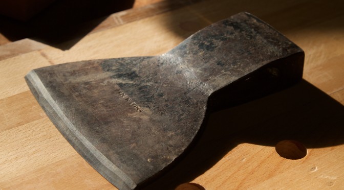
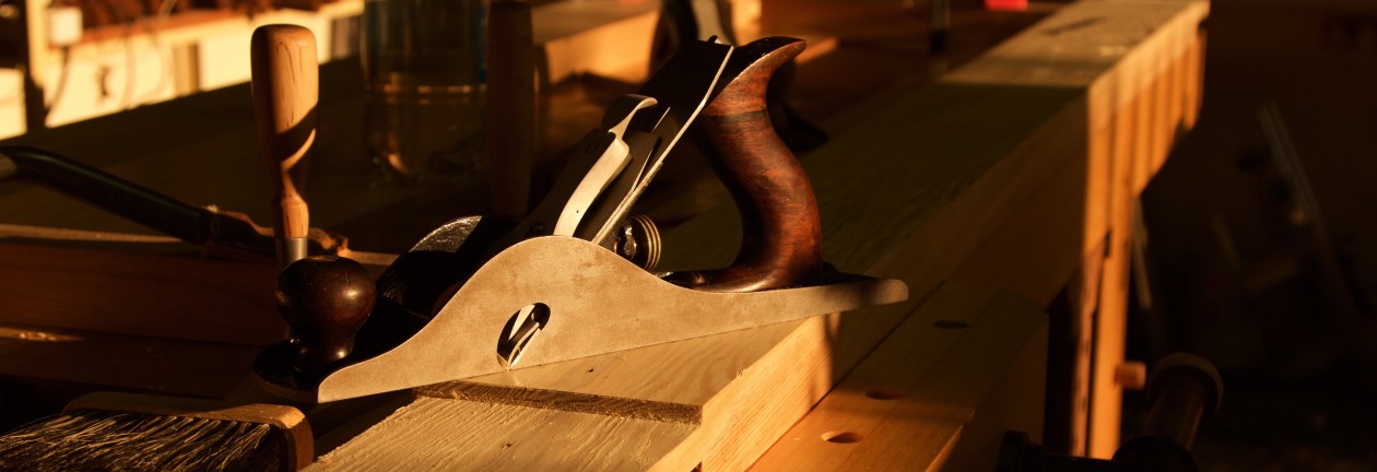
As usual, my shop made scrub plane made short work of removing heaps of material.

IMG_6309

Here you can see the aggressive camber on it’s Lie-Nielsen blade.

IMG_6310IMG_6311

I did the fine tuning with a circa 1896 type 8 no. 8 Stanley jointer plane (not pictured).

IMG_6313IMG_6312

Rail stock prepared and awaiting the next assault on it’s integrity.

IMG_6316

In the meantime I dug out some Tasmanian Blackwood that my father used to build crates to transport all his tools to my current shop 5 years ago. I really like using and reusing wood like this. It adds value to the story of the piece of furniture. In fact, every bit of timber in this bed used to be something else in a previous life. The Scots pine comes from a crate that was used to transport a massive machine from Germany to Namibia.

The Tasmanian Blackwood were processed to become the slats of the bed.

IMG_6318

Cutting the Scots pine for the legs.

IMG_6319IMG_6321IMG_6322

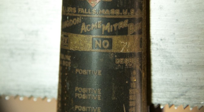
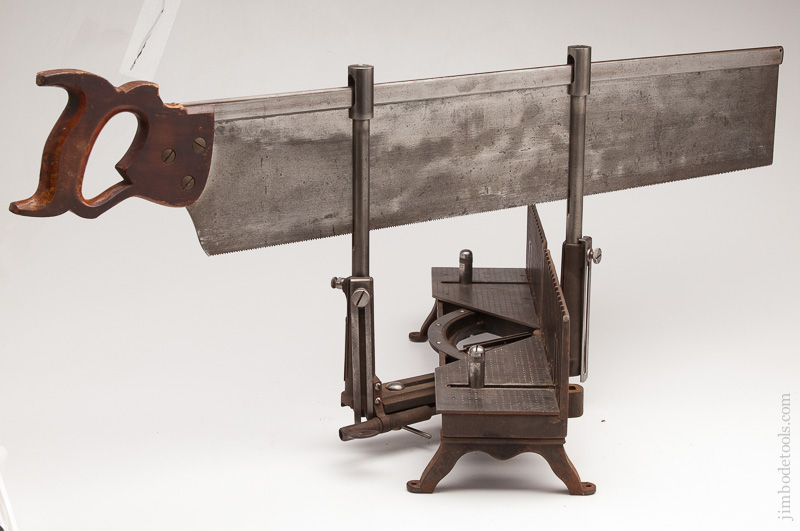
Just have a look at how perfect it came out of this legendary Landgon Miller’s Falls no. 75 ACME Mitre saw box.

IMG_6323

Squaring up the leg stock by hand planing.

IMG_6325

I did the measuring out of the tenon locations by using the actual pieces as they were destined to fit together. As you can see that all transpired on my shop made assembly table.

IMG_6326IMG_6327

The Langdon mitre box also came in very handy to cut the shoulders of the tenons. You can see the stop on the arms that allow one to set the exact depth of cut. The cheeks were cut on the band saw.

IMG_6328IMG_6329IMG_6331IMG_6332IMG_6333IMG_6335

I usually employ my Stanley no. 10 rabbet plane to plane the cheeks down to the exact measurements.

IMG_6340

The slots for the tenons in the top of the legs had to be as close to perfect as possible as it is very difficult to remove material after the sawing is done. Therefore I took to it with my Bad Axe Roubo Beast Master. You will notice the three short cuts in the waste which I made to warm up. Completing this many monster cuts by hand certainly saves on Gym membership.

IMG_6350IMG_6349IMG_6351IMG_6353

The waste was removed with my shop made bow saw followed by chiseling.

IMG_6354IMG_6355IMG_6356IMG_6357

Legs being cut to final length.

IMG_6362IMG_6363

Next up, the fitting of the massive tenons into their respective slots.

IMG_6364IMG_6365IMG_6366IMG_6367IMG_6368IMG_6369IMG_6370IMG_6371IMG_6372

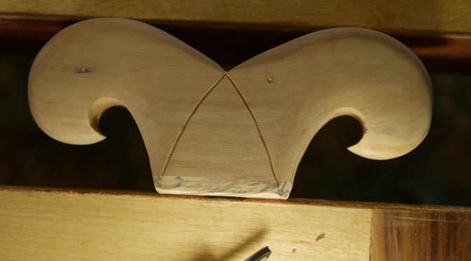
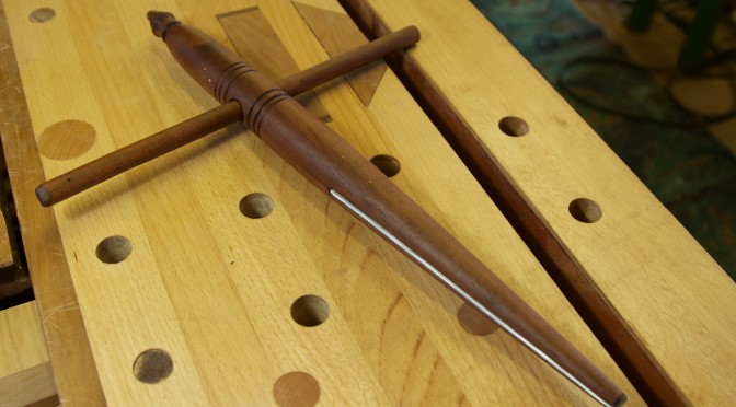
Once both tenons for each leg fitted perfectly, I used a shop made marking knife to mark out the exact location for the two slots where the tenons hook into each other.

IMG_6373IMG_6374IMG_6375IMG_6376IMG_6377

The picture below should give you an idea of what the tenons look like in the end. They hook into each other inside the slots at the top of the legs. This is a surprisingly sturdy joint, even in the absence of any adhesive. The absence of adhesives allow the wood to move freely during changes in ambient humidity and it is also easy to take apart in future to collapse the bed for easier transport.

IMG_6381

My second commission – part 3

26/10/2015

Way back at the end of October last year, I started planing the Kershout for this table. As you can see from this picture, I had first class help in the form of my wife. She helped me to feed the boards to the planer as they are far too big and heavy to manage by myself. She did all of this while sporting some or other tinfoil-toe-treatment-thingy. Heaven knows whether it is for cosmetic or functional purposes. She is training for the world famous Two Oceans Ultra Marathon (56 km) so it might be something to do with that (I do not want to know), or simply a type of African pedicure??

Anyway, the Kershout were planed bit by bit over a 4 month period. This ensures that it has enough time to settle between planing sessions, which usually results in less warping.

IMG_5363IMG_5365

7/3/2016

The timber mill day.

On Saturday I took to the Witpeer for this project with a vengeance. It has been sitting in the shop to acclimatise for about 5 months now. Given the amount of processing to do, I asked my gardener (this is Africa aka TIA) Adam to help. We identified and marked out the pieces for the trapezoid shaped leg, which was first cut into shorter pieces using my Disston no. 12 crosscut handsaw

IMG_6299IMG_6300

From left to right: The shorter pieces for the trapezoid leg, four long strips for the beam at the bottom of the table, with a bit more trapezoid leg pieces sitting on top of it, and the Kershout pieces for the top which received its final planing pre glue-up.

IMG_6302

Trapezoid leg pieces.

IMG_6303IMG_6304

I usually try to clamp the pieces as shown below after each of the planing/cutting steps. With each of these steps you release tension, which tends to make these feral boards move like Michael Jackson.

IMG_6314IMG_6315

Now I often refer to the timber as being feral and I do not think most people realise exactly what I mean. Here are a few pictures to illustrate what I mean. For every bit of stock I want to use I usually have to laminate carefully chosen bits of timber together. In order to make up the necessary dimensions of the beam for this table I had to liberate four strips of Witpeer from wild boards such as the one pictured. You can appreciate the cracks, changes in grain direction, and changes in colour.

IMG_6341IMG_6342IMG_6343

Therefore I have to whittle out relatively defect free timber to laminate into stock of larger dimensions. This takes a lot of time and effort as you can imagine. All this happens prior to being able to start really shaping pieces of furniture, hence my very pedestrian progress most of the time.

IMG_6344IMG_6345

Here I am hand planing a straight edge on one of the pieces to use as a reference surface for the table saw to cut the opposite edge parallel to the aforementioned. This wood is so hard that you really do need power tools for same of the steps.

IMG_6346

Resting in clamps overnight.

IMG_6347IMG_6348

The next day saw the strips being prepared a bit more with a final planing and sanding to create the best possible glue surface. Then the glue-up.

IMG_6358IMG_6359

Now we have a piece of timber of appropriate dimensions to start shaping into a beam for the table.

IMG_6360IMG_6361

I removed the excess dried glue with my shop made flush plane.

IMG_6378IMG_6379

On wards and upwards, they say.

Swedish side axe

3/8/2015

I found this single bevel axe head in a “cash converter” store in George while visiting the Garden Route in June 2015. I had to fork out the astonishing amount of R125 for it. (bottom of the first picture)

IMG_4850IMG_4852

Some idiot put a bevel on the non-bevel side, but otherwise it was in top shape.

IMG_4853IMG_4854

The only mark on it reads “Made in Sweden”.

IMG_4851

29/1/2016

First I had to get rid of the unwanted bevel and then proceeded to grind a fresh bevel on the correct side of the head. This took quite a while as I was careful not to overhead the steel, which would result in a loss of temper. You can see how I clamped the axe head to a piece of timber which is shoved against a suitably place object (read foot) to ensure a constant grinding angle.

IMG_6004IMG_6005IMG_6006IMG_6045IMG_6046

The handle was made from a piece of Assegaai (Curtisia dentata) using the bandsaw, draw knives, rasps and a card scraper.

IMG_6047IMG_6049IMG_6061IMG_6062

1/2/2016

I am proud to report that I did my first bit of blacksmithing to create this cold steel wedge. It was a scrap bit of steel that received an almighty pounding. I do not have a blowtorch (yet), but can report that aggression can sometimes yield products of beauty. The steel is soft enough  to be shaped without heating.

IMG_6133IMG_6134

As you can see here, I used a wooden wedge and the metal wedge to secure the handle.

IMG_6141IMG_6143IMG_6144

Of course I drove the metal wedge one blow of the hammer too far, which resulted in the timber below the axe head splitting.

IMG_6142

As I was not in the mood to make a new handle, I simply installed a wood screw to inhibit a potential extension of the split.

IMG_6145IMG_6161

15/2/2016

To complete the rehab I made a nice game leather sheath for the side axe. Now the only thing left to do is to find suitable green wood in Namibia to hew into chair stock.

IMG_6226IMG_6227IMG_6228IMG_6229

The Fountainhead – part 2

15/2/2016

The first post in this riveting series can be found here.

So after all the drama of the past 11 days we can get back to the usual business of documenting a slow, yet delightful woodworking journey. The jaws of my fountainhead were fixed to the arms using slow setting epoxy and an almighty Assegaai draw pin. As I mentioned in the previous post, one should be carefully not to offset the hole through the tenon by too much if working with such extremely hard wood as this. You will be able to appreciate from the pictures below, how the excessive offset I used caused an obvious deviation in entry angle on the entrance side. You will also notice the gap on the exit side. If the offset was even slightly more it would have destroyed the jaw on the exit side.

IMG_6217IMG_6218IMG_6219IMG_6220

A quick test fit.

IMG_6221

Here you can see the so called leather hinge.

IMG_6222IMG_6223

Driven by my shame regarding the issue of copying some else’s design, I decided to created my own unique clamping mechanism. It all started with a laminated block of Kaapse Swarthout (Maytenus peduncularis).

IMG_6225

Which received an Ysterhout (Olea capensis macrocarpa) footing. The tool supermodel is obviously pre-glass-door-incident. The photos should paint a fairly comprehensive picture of how I went about shaping this wing nut on steroids.

IMG_6230IMG_6231IMG_6232IMG_6233IMG_6234IMG_6235IMG_6236IMG_6237IMG_6238

IMG_6239IMG_6240IMG_6241IMG_6242IMG_6243IMG_6244IMG_6245IMG_6247IMG_6248IMG_6249IMG_6250IMG_6251IMG_6252IMG_6254IMG_6255IMG_6256IMG_6257IMG_6258IMG_6259IMG_6260IMG_6261IMG_6262IMG_6263IMG_6267IMG_6268IMG_6269

… and Bob’s (Demers) your uncle.

IMG_6273IMG_6274

The final product with a Cape Brewing Company craft beer in the background. Imagine a fountain of craft beer … Sorry I got a bit distracted there.

IMG_6288IMG_6287IMG_6289IMG_6290IMG_6292

You should be able to see the seal leather grip on the inside of the jaw in this picture.

IMG_6294IMG_6297

The shape of my giant wooden wing nut was inspired by my idea of the head of a fountain.

IMG_6295

My second commision – the prototype phase

8/2/2016

Previous posts in this series can be found here and here.

Seeing that this table will be one of the major projects for the year and the first significant piece of furniture to emerge from my current shop, I decided to first build a prototype. I have never done this before, but can already see that it is a vital step in the right direction. Just to remind you of the background, this is a table for friends of ours the Burmeister-Nel family. I am building the table as payment for a whole stack of excellent Scott’s Pine beams.

The design of this table has evolved significantly over the past 7 months. So far the evolution took place in the realm of my personal cerebral SketchUp. The prototype is the first tangible manifestation of the mentioned neurophysiological exercise. At this stage it is primarily inspired by George Nakashima and Japanese joinery ideas. The feral nature of the African hard woods we chose for this project really lends itself to the Nakashima design ideology.

A second prominent influence in this design effort would be the ideas and techniques used by pre-industrialisation artisans as explored by George R. Walker and Jim Tolpin in their seminal work “By Hand & Eye”. I tried to use those techniques to strike the sweet spot in terms of proportion between various parts and their relation to one another. What I found was that working with simple whole number ratios makes it very easy to shrink and expand the design for the purpose of the prototype.

The starting point was the size of the top, which ended up being a 1:2 rectangle. The hight of the table that worked well was 2/3 of the width, which meant that the whole piece would fit in a 2:3:6 cuboid.

IMG_6162IMG_6163

Here you can see my initial sketches to work out appropriate proportions. The side view were divided into 5 equal parts and I placed the leg structures on a 1:3:1  rhythm. The angle of the leg structures were also derived using a similar approach.

IMG_6164IMG_6165

I used some of the mentioned Scott’s Pine to build the prototype as it is easy to work with.

IMG_6166IMG_6167IMG_6168

15/2/2016

I made the effort to plane down the top to the exact thickness relative to the size of the model.

IMG_6270

The solid trapezoid shaped leg piece is twice as thick as the top and all the other parts are related to the thickness of the top.

IMG_6271

The heavy beam at the bottom that connects the leg pieces will be attached to the trapezoid shaped piece with a through tenon, which will receive a wedge similar to the one pictured.

IMG_6275IMG_6277IMG_5544

The opposite leg piece will consist of four spindles ascending at the same angle as the sides of the trapezoid piece. These are not the correct size as it was impossible to produced such small spindles, so the wire had to do. The actual spindles will be slightly thicker and have the bamboo type appearance similar to spindles used in some Windsor chairs.

IMG_6279IMG_6280IMG_6281IMG_6282IMG_6283IMG_6284IMG_6286

Here are a couple of photos illustrating the type of design I have in mind for the spindles. I refer to the spindles in the back of the Windsor chair rather than the legs. I add these pictures in response to Stefan’s valid feedback.

1-P1070729BambooHoopbackWindsorSideChair02

I would like to invite everyone to give input on the design. Please feel free to rip into it, if I feel too aggrieved by the criticism I can simply ignore it. Hopefully though we can fine tune it to be better. At this stage I am fairly happy with it, but am quite sure it can be improved a bit.

The Tool Supermodel

24/2/2016

I want to apologise for my absence from the woodworking blogosphere over the past week. Unfortunately we’ve had a really horrible time, but learnt in the process that we are very blessed with wonderfully supportive friends and family. If you read this blog you will most definitely know the Tool Supermodel.

IMG_6230IMG_6131IMG_9604

The Tool Supermodel decided to run through a glass sliding door last week. Being Africa it turns out that it was not furnished with the correct type of glass. She ended up with a massive cut on her upper inner arm that sliced through two arteries and several nerves. She very nearly died as a result of blood loss, but they were able to sort out the vascular side of things here in Windhoek. That took about four hours. The next morning Aoife and her mother were flown out to Cape Town to get the nerves sorted. She then had another 5 hour operation, in CT which went well.

I joined them in CT over the weekend and we all flew back to Windhoek on Monday. Now we have to wait 3-6 months to see whether the nerves will grow back. To top it all, they broke into my practice on the night of the initial surgery and stole almost all our PCs. That meant that I was not able to work the following day and we are still in the process of getting the practice up and running again.

So that is why I have been absent for a while. I trust that it is a valid excuse.

The fountainhead – part 1

1/2/2016

Seeing that my planer is still in ICU I am continuing to do the odd little jobs that does not get done once the major projects start in all earnest. One of those jobs that has been on the list for a few years is a shop made saw vise. Once again my e-mail advisor Mark Harrell of Bad Axe Tool Works sent me in this direction. He told me about an article in the August edition (#219) of Popular Woodworking by Jason Thigpen. Apparently Mark is using one of these himself and finds it exceptional.

IMG_6119

I found scrap pieces of beach and something I though was Tasmanian Blackwood for the job. At this stage I think it might actually be Walnut, but I am not too sure. While living in New Zealand I restored a few riffle stocks of Walnut and this seems to be quite similar. I am a bit confused about where it came from though. Clearly it was in my father’s pile of wood that came my way, but I do not recall him ever using walnut for any project.

Unfortunately both piece of scrap were significantly twisted, but fortunately thick enough to be planed out. Both these species are so hard that it took me a whole day to get rid of the twist, and square up the four blocks all by hand.

IMG_6118

Marking out the tenons.

IMG_6120IMG_6121IMG_6122

Sawing the tenons.

IMG_6124IMG_6125

Sawing the shoulders.

IMG_6127IMG_6128

I usually stay about 1 mm away from the knife line with the saw and remove the rest by horizontal pairing ala Charlesworth.

IMG_6130

That bit of waste next to the knife line also serves to protect the actual shoulders while I plane the cheeks of the tenons to it’s (almost) exact thickness. I use my Stanley no. 10 rabbet plane and a set square to achieve this.

IMG_6135IMG_6138

A quick change of handle for my Lie-Nielsen chisel. I turned this pairing handle myself, which is one of the wonderful advantages of these socket chisels. The longer handle makes for more accurate and comfortable pairing.

IMG_6140IMG_6139

As you can see here, this Charlesworth method can be frightfully accurate.

IMG_6148

This area was removed on the table saw. I am sure you will excuse me for not wanting to plane unnecessary by hand at this stage.

IMG_6150

It got cleaned up with a Stanley number 78 rabbet plane. No sweat.

IMG_6151IMG_6152

The mortises were first drilled out on the drill press and then fine tuned using a few chisels. The wood was simply to hard for my brace and Irwin auger bit, which is why I had to resort to the drill press.

IMG_6154IMG_6155

8/2/2016

IMG_6169IMG_6170

One of these elevated areas will become the actual jaw of the vise. The other was kept intact to make drilling these holes easier.

IMG_6172IMG_6173IMG_6174IMG_6175IMG_6176IMG_6177

Here I am fine tuning the actual jaw surface. Jason dubbed it a “compound springjoint”. What that basically means is that you first remove a bit of timber from the bottom of the jaw to ensure that the first contact between the jaws occur at the very top of the vise. As the tention increase the slight distortion (bending) of the arms results in the entire jaw face clamping down on the saw plate.

Once that is accomplished you hollow out the length of the jaw by a smidgen. This in turn will ensure that the ends of the jaws make contact first. As the clamping pressure increase the small gap in the middle close up and you end up with even pressure across the whole length of the jaw faces.

IMG_6178IMG_6179IMG_6180

The area I mentioned earlier that was left intact also helped to keep the jaws stable on the bandsaw for this operation. One of the curves were too acute for the bandsaw so I had to use my shop made bow saw.

IMG_6182IMG_6183IMG_6184IMG_6186

At this stage the little area pictured had served it’s purpose and was removed by hand planing, (after an ice cold beer). You would also put ice in your beer if your shop averaged 33-35 °, trust me.

IMG_6187IMG_6188IMG_6189IMG_6190

The table saw once again came in handy for this angled cut.

IMG_6191

As you can see the table saw left nasty burn marks, which were removed by hand planing.

IMG_6192IMG_6193

The second bevel were all done by hand planing.

IMG_6194IMG_6195IMG_6196IMG_6197

Next came the so-called “leather hinge”. It is an appropriately sized block of wood with leather on both sides that keeps the arms parallel to each other. If you read Jason’s article it will become a bit clearer.

IMG_6198IMG_6199

By the way, you might be able to see by how much I chose to “off-set” the draw pin holes. As it turns out this is slightly too much. I realised by doing this that for extremely hard wood like this one should use less. Nothing disastrous happened but if the off-set was anymore I would have destroyed many hours of toil during glue-up.

IMG_6200

Here you can see the leather hinge and (as per usual) my hardware improvisation.

IMG_6201IMG_6202IMG_6203

Unfortunately I did not take a photo of the crucial step of drilling the holes for the two bolts that pass through both arms and the leather hinge. I employed insert nuts to anker the bolts. I used to struggle with these insert nuts. They never used to seat nice and straight. That is until I made this incredibly complex insert-nut-inserter. You screw the insert nut onto the device with enough of a leading section of threaded rod which keeps the nut lined up and launch it with your cordless drill.

IMG_6204IMG_6205IMG_6206

So why the title “The Fountainhead”? I happened to listen to an audio recording of this classic 1943 novel while working on this project. At some stage I realised that the saw vise actually resembles the head of a fountain.

Warning: This post will now deteriorate into a pseudo-philosophical discussion of literature rather than woodwork. Please refrain from reading any further if you are allergic to such quasi-intellectual drivel.

The novel seems to be quite relevant to the sentiments expressed by many woodworkers that forms part of the resurgence in handcrafted furniture. There seems to be an underlying theme  that permeates through most of what is written online by the new generation of woodworkers. The theme can be seen as a reaction against consumerism (gone crazy), industrialisation and it’s decaying effect on quality. The Schwarz has in recent years linked it to American Anarchism.

Interestingly though, one of the main themes of the book is at odds with one of Christopher Schwarz’ ideas. He often argues that most designs that stood the test of time can probably not be improved on. I am particularly thinking of his ideas around workbench design. The main protagonist in the Fountainhead, Howard Roark challenges this idea with his approach to architecture. He is fiercely opposed to any form of copying. So it was with shock that I realised that I was pretty much copying Jason’s saw vise, which I usually do not like doing. Of course a workbench and a building is two different things, but it is interesting ideas to mull over on your journey towards your own philosophy. There are no rights and wrongs I am sure, just concepts to ponder over for woodworkers with a philosophical bent.

One more observation I made was extremely thought provoking. Probably the major theme portrayed through this story is that of individualism being more desirable than collectivism. According to the novel the individual should produce work that is true to themselves and original. They should not merely give the masses what they want, which is usually a slightly tweaked version of what has been done ad nauseum  in the past. What seems to betray this prime philosophical stance of the book, is the fact that in true American style it has a fairly happy ending. In other words, what the masses want.

Anyway, I think that any modern woodworker can benefit from reading this book. It will get you to think about and challenge your beliefs around design and woodworking in general.

I conclude this post with a picture of a Shaft-tailed Whydah (bottom) and a Redheaded Finch (top) that came to visit my shop this weekend. We will hopefully finish the project in part two.

IMG_6214

Accurate sawing, off the grid – Miller’s Falls Langdon mitre box no. 75

16/7/2015

It has been quite a few years now since becoming disillusioned with the DeWalt radial arm saw that used to belong to my father. I used to think that it is the best thing since cream cheese, but realise more and more as time went on how inaccurate  and dangerous the thing is. It takes ages of fiddling around and making copious test cuts to get it to saw square in two different planes. Then you might get two descent cuts and before you know it the blade grabs the stock and the setting is lost again. It also tends to burn the incredibly hard African timber I work with.

So I decided to look for an alternative solution. My research into the topic of mitre saw boxes confirmed that the Langdon ACME no. 75 would be my first choice. Some of the literature on the Old Tool Haven website suggests that “the Langdon Acme miter box represented the zenith of the Langdon Mitre Box Company’s achievements“.

After waiting patiently for the desired mitre box to become available, I finally bought a Langdon ACME from Jim Bode. Kathryn who is my usual contact person at Jim Bode Tools, was so kind as to send the Simonds saw (that came with it) to Mark Harrell at Bad Axe Tool Works for a sharpening. 

Mark had the following to say about the mitre box/saw combination: “NICE score on the Millers Falls No. 75 miter box setup. I have the exact same large miter box and saw here at the shop. The saw’s manufacture happened at some point BEFORE 1928, when Simonds abruptly ceased making hand and backsaws. There’s a bit of a mystery surrounding that, because they were competing quite nicely against Disston. My theory is some sort of dope deal transpired between the two manufacturers. I do know that of all Disston’s competitors (that they couldn’t either drive out of business or buy out), Simonds’ quality and marketing ran toe-to-toe against Disston. In any event, they quite surprisingly quit making hand and back saws in 1928—so, your saw pre-dates that.”

306194306278306270306274

I tried to zoom in on Mark’s dating by looking at the mitre box. From looking at the Old Tool Haven write-ups the saw box was made after 1906 when Millers Falls bought the Langdon Mitre Box Company as mine has the Miller’s Falls brand name on it. Further more it has a 1909 patent date on it, thus after 1909 then. The pictures below show how the plate looked like before the Miller’s Falls takeover and what the mitre box in question looks like.

langdon-acme-lgIMG_6112

The following picture from the MF 1939 catalogue show a slightly more evolved mitre box, so mine should be older than that.

MF 1939 catalogue

I then had a look at the saw to see if that can help us to zoom in on the date of manufacture. I already knew it pre-dates 1928 from Mark Harrell’s information. According to the Saw Nuts website this medallion was used between 1922-1926. Thus this setup was probably manufactured during the early to mid 1920’s.

IMG_0374

 26/8/2015
The mitre box finally arrived on the above date.

IMG_5060

17/9/2015

As a result of making a detour via Bad Axe Tools, the Simonds saw arrived a month later. Mark did an absolutely brilliant job of sharpening this beast, it is lethal.

IMG_0362IMG_0363IMG_0370IMG_0372IMG_0373

21/1/2016

I noticed that although I took every precaution to set it up perfectly, the saw drifted ever so slightly to the right. Luckily my personal tool historian/magician Bob Demers (The Valley Woodworker) mentioned to me last year that it might well do something like that. I therefore asked him how to fix the problem. This was his advise:

After making sure that the box is mechanically “tuned” to cut 90 degrees and the saw sharpened correctly. Having been done by no less than Harrell, you bet it is,

then comes the fine tuning of the saw set.

Unless the saw sharpener has the box with him, it is impossible for him to know witch way to tweak the saw set.

You see if the saw want to naturally favour one side or the other (Not following a straight line) it is because there is a tad more saw set on the offending side and it is compound by the small mechanical errors introduced by the box mechanisms .

The set being slightly more on that one side the saw is cutting an asymmetrical kerf and want to drift toward that side.

Think of two guys  paddling a canoe. If one guy is paddling a tad stronger on one side, the canoe will drift toward that side.

We are not talking of much of a difference so go easy….

The way to fix that is by GENTLY running a mill file (no handle) with NO pressure or a oil stone (must be flat, and never a waterstone, too soft)  on the side the saw is drifting toward

That action will just abrade the tip of the offending saw tooth set. Go easy, you do not need much to teak it.

Re check the action after each pass, often 1 or 2 pass is all that is needed.

You will probably hear or feel the file when it catch the offending proud saw tooth.

So if that is all, why don’t the saw filer do that themselves?

Because even if the saw was perfectly tuned to go straight, there is still some minutes  mechanical things in the box itself which could force it ever so slightly left or right

What we are doing in effect, is tweaking THAT saw for THAT mitre box

Hence why you must ensure first to eliminate all gross errors in the box mechanism and ensure that the saw is travelling true.

Once that is done, it is simply a matter of tweaking the set of the saw to achieve a true cut.

To test how true the saw is cutting, flip over one cut piece and put it back against the other fresh cut. They should lay flat and straight.

The error you see is TWICE the actual error that way

NEVER force the saw to correct a wandering cut. ALWAYS let the saw cut the way it wants.

As we often says: Get out of the way, let the saw cut. It want to cut straight that way, let it

Once the saw AND the box are adjusted to each other, it is possible that a check with a square will reveal a small error, but the saw will still cut square.

It is adjusted to that box…

At this point it is a wise idea to some how identify THAT saw goes with THAT box… Just saying, especially if you have a “few” 🙂

Once you get it as close as you can get it, just remember that other ultimate weapon at our disposal: A shooting board and a freshly sharpen heavy plane 🙂

Hope this answer your question.

It is faster and easier to tweak it than to write about it 🙂

NEVER used a long mitre saw (23 to 28 in long), free hand outside its box. It will bend

The spine is not strong enough to resist bending forces, it is designed to be restrained by the saw box guides.

Now if that is not a master on this topic then I do not know who is!! Thanks Bob!

So that was exactly what I did and true as Bob (pun intended) it took two light touched with the mill file and it was humming to a perfect 90 degree with every single cut.

IMG_6108IMG_6109IMG_6110IMG_6111

I know Patrick Leach often speak of the “tool model”. I mean no offence to Patrick, but I think this is the tool supermodel of the woodworking blogosphere. I might be slightly biased, but what the heck.

IMG_5934IMG_5935IMG_5936IMG_6117IMG_6029IMG_6028

As you can see here the cut is sublime, all credit to Mark Harrell.

IMG_6031

Upgrades to my split-top Roubo bench

21/1/2016

It is almost a year since I finished my first Rouboesque bench, which gave me ample opportunity to see which design features works for me and which does not. One of several reasons (discussed in detail in this post) why I decided to go with a split-top design was to be able to have easy access to clamp work using f-style clamps along the centre of the bench. I therefore sized the sliding tool trays in such a way that there would always be gaps between them for the above mentioned clamping activities.

What has become apparent over the past year is that although this is a very handy feature I do not need it all that often due to the number and positioning of the holdfast/dog holes. I am able to use holdfasts for 95% of that type of work holding. To add to that, the gaps between the sliding tool trays constantly threaten to swallow tools which the end up crashing into the planes on the shelve below the bench top.

For these reasons I came up with a fairly easy solution. I made two gap fillers that can easily be removed. The pictures should make it clear how it works. The bigger one of the two now act as a more traditional type tool tray that can hold plenty of tools below the surface of the bench top. These gap-fillers do not interfere with the sliding tool trays at the top, which can still slide to expose the tool trays below them.

I hope that the series of photos that follows will make it clear how these minor tweaks prevent the bench from swallowing tools yet retains easy access for clamps when needed.

IMG_6007IMG_6008IMG_6009IMG_6010IMG_6011IMG_6012IMG_6014IMG_6015IMG_6016IMG_6017IMG_6019IMG_6020IMG_6022IMG_6024

Shop made reamer and tenon cutter

25/1/2016

I am currently  in an unwanted limbo phase in my shop. My electrical planer was sent to a workshop to get fixed end of last year with the idea that they can get it sorted while I am away on holiday. Unfortunately the curse of Namibia has befallen the planer. They are waiting for parts from some other godforsaken place before they can finish the job. That has forced me to keep myself busy with some of those little jobs that you keep on putting off while working on bigger projects.

One of the fairly quick projects I got stuck into on the weekend was to build a reamer and tenon cutter set. I bought an electronic version of Christopher Schwarz’s new book “The Anarchist Design Book” (highly recommended by the way) last week, which reminded me that I wanted to build such a set. A few people have already written stuff on the detail of how to build such a reamer so I will not repeat all that. Here are a few links that I found helpful.

Greenwoodworking

Peter Galbert

Tim Manney

Gluing Assegaai (Curtisia dentata) for the reamer.

IMG_6026

While that was curing, I used a piece of hacksaw blade to shape the blade. It seems that most of the authorities (including the Schwarz) prefer a 6° angle for the blade. That is exactly what I decided on. It took ages to shape this blade as it is ridiculously hard and I did not want to ruin the temper.

IMG_6035IMG_6036IMG_6037IMG_6050

The next day the Assegaai shaft was turned on the lathe.

IMG_6051

The most frightening thing about making one of these reamers is cutting the kerf to accommodate the blade. The only handsaw I own that would be able to cut such a deep rip is my humungous Disston no. 12 26″ 6 tpi. Now imagine cutting such a precise kerf in a relatively delicate piece of wood with a saw like that. I had to first consume a few drops of usquebaugh before making the cut.

IMG_6052IMG_6053

… and Bob’s your uncle!

IMG_6060IMG_6057

Then the idea is to use your new reamer to produce a perfectly matched conical tenon cutter. For this purpose I went foraging for a suitable blade. Was I not over the moon to find this beauty. One of the dilapidated old wooden planes I bought some time ago for decorative purposes happened to sport this blade/chipbreaker combination. As you can see we have a Robt Sorby blade with a A. Mathieson & Son chipbreaker.  As far as I know, this is seriously good stuff.

IMG_6038IMG_6039IMG_6042IMG_6040IMG_6041

Scrap piece of Tasmanian Blackwood.

IMG_6063

5/8″ hole drilled through it.

IMG_6064

Reamed out to the point where the blade is only just touching the edges of the far side of the hole.

IMG_6065

Despite cutting a type of escape rout for the shavings in front of the blade (as recommended by the gurus), I found that you have to stop quite often to remove clogged up debris.  Despite that it is a legend of a tool to use. You have perfect control and no loud noise or dust to contend with.

IMG_6068IMG_6067

I think I need to get a few more pointers from Jonathan White (The Bench Blog) on photography, because I could for the life of me not capture this nicely. The reamer managed to ream out a hole that has sidewalls as smooth as the usquebaugh I consumed earlier. I had to put on sunglasses to deal with the glare of the midsummer sun rays bouncing off of it.

IMG_6072

Opening up the hole carefully by planing away the waste. Initially quite aggressively so.

IMG_6073IMG_6074IMG_6075

Then quite carefully with my David Charlesworth powered no 5½.

IMG_6076IMG_6078IMG_6081IMG_6082

I used the following methode to secure the blade into position.

IMG_6087IMG_6088IMG_6089IMG_6090

Then you only need to turn a dummy tenon as close to the correct size/shape as possible on your lathe. The dummy becomes the first victim of your tenon cutter and can be used as a guide to check your progress while reaming mortises in future.

OK, time for some more usquebaugh.

IMG_6103IMG_6104IMG_6105IMG_6106