All posts by Gerhard Marx

Psychiatrist and Woodworker

Another scratch awl

11/11/2013 – Last week I took some of the beech left over from my plane building phase, laminated two bits and used it to turn some handles.

IMG_8476


The idea was to turn a handle of similar design for a second scratch awl and one for a chipbreaker/capscrew screwdriver.

IMG_8543

This is the handle that became the alternative scratch awl. I wanted an awl that is designed to make holes for accurate drilling as apposed to scratching/scribing lines at which my first shop made awl excels.

IMG_8547


The punch I used was epoxied, tapped in and then clamped in position by the tight fitting ferrule.

IMG_8521IMG_8522

I stuck the awl in the drill press to tidy up the copper with sandpaper.

IMG_8525IMG_8526

After a treatment with tung oil and Wooddock it is posing with it’s brothers and sisters. These are all shop made marking tools.

IMG_8565IMG_8566IMG_8567IMG_8568IMG_8569IMG_8570

My 18th Century Workbench in progress 1

Research and Dreams

8/11/2013 – A couple of weeks ago I realised that I would be able to fit my dream (proper) workbench into the shop space I already have. Until recently the idea was to only build this bench once my shop has been enlarged somewhat. Then one evening while packing a few things away before heading down to the house, I suddenly saw how the bench could fit quite easily with only a relatively minor reorganization of some power tools.

Since then my research, reading and thinking about the design of the bench sparked up again. I started re-reading the two books by Christopher Schwarz on designing and building traditional workbenches. I bought the article he wrote on building a Holtzapffel bench quite some time ago and re-read that as well..

workbench 1Y1532

This is an example of a Holtzapffel bench I found on the internet. My bench will be a version of a Holtzapffel and I particularly like the design of this one with the split top. Mine will probably have a bit of a wider gap to make it easier to get a F-style clamp through. I also plan to use a twin-screw vise as a face vise (same as the bench below) and a legvise on the opposite side in the face vise position. This is because my bench will be place so that one can work on it from all sides, rather than against a wall. I hope that my son will one day join me in the shop so the two face vises will enable us to work simultaneously and provide a wider range of options while I work by myself.

The end vise is still at a stage were I am weighing up different options. At present I am leaning towards using a smaller twin-screw vise, which could enable me to use another row of dog holes on the opposite side of the bench.

DSCN4223

Just another example of a Holtzapffel bench. I will aim to also have a shelve low down between the stretchers, such as the bench below.

2653733724_e62bcca568_z

I really like the look and strength of these through mortise and tendon joinery that seems to be very commonly used on traditional Roubo benches. I am planning to use it for my bench.

roubo5roubo_workbench2

The bench below show what I plan for the opposite (to the twin-screw) side of my bench to look like. A leg vise with a sliding deadman.

roubo_0214777833813_5743c5301e_b


This afternoon I want to go and find, or more likely order, beech boards for this project. The idea is that the wood can then settle/acclimatize (in my shop) over the next 6 months or so until I have moved the power tools that needs to be moved (which will include building a few cabinets) to create the space for the bench.

As you would expect by now I plan to use only Lie-Nielsen hardware for all my vises.

facevise_IMG_6577lie-nielsen-front-mounted-vise_smsq


chain_drive_vise_02underside_IMG_6581


leg vise

Lie-Nielsen customer service

6/11/2013 – I would like to thank everyone at Lie-Nielsen, and in particular Deneb Puchalski, Kirsten Lie-Nielsen and Jillian McCrohan for their superb customer service. It has been my consistent experience that these guys go out of their way to help poor sods like me who are stuck in woodworking-hinterland. Otherwise known as Africa, or more specifically Namibia. For customers like me they probably spend more time and effort to get my orders sorted than what would be economically profitable.

Over the past few weeks they have responded to heaps of e-mails and came up with ingenious plans to help me. They are not scared or reluctant to give me advise when I decide to try and build a tool myself to cut down on cost as you can imagine what the shipping to Namibia adds up to. When I do order some of their gold standard tools, they simply leave no stone unturned to make sure that it gets to me safely.

Due to my geographically-challenged-status, I end up having to buy everything I need via mail order and can honestly say that Lie-Nielsen has been the only company willing to deal with all the challenges of getting stuff to my Deep Dark African hideout.

So thanks a lot guys and viva Lie-Nielsen!

Ruler stop

3/11/2013 – This has been one of those ridiculously small tasks that I’ve been putting off for ages. My assembly table has a steel ruler close to it’s edge and inlayed flush with the surface. If you are interested to see how I’ve built this table you will find several chapters documenting the process in detail under the category “Bench” on this site.

Anyway the idea of having the ruler there is to speed up basic layout tasks such as marking out lengths of pieces of stock. In order to really make this easy one needs a stop at the zero end of the ruler so you can simply butt the one end against it and mark the appropriate length. In the picture below you can see what I mean.

IMG_8484IMG_8485

The stop is simply a small piece of scrap Assegaai with a 6 mm hole accepting a bolt which slots into the T-channel on the side of the table’s edge, fixed with a few turns of a wing-nut. When it is necessary to remove it, it is simply flipped through 180º and it sits below the table’s surface. You will notice that the ruler was positioned so that the edge of the table is zero even though it does do run all the way to the edge.

IMG_8486IMG_8487IMG_8488

Shop art

1/11/2013 – In order to establish a creative environment in my shop, I decorate the walls with my children’s art. This post shows some of the their art that is already inspiring me. From Didier’s art it should be quite obvious that we live in Africa. My daughter is going through quite an abstract phase.

IMG_2160

Didier Jan Marx

IMG_8509


IMG_8510


IMG_8511


IMG_8512


IMG_8513


IMG_8514


IMG_8519

8/9/2014

IMG_2158IMG_2159IMG_2164IMG_2165


Aoife Isi Marx


IMG_8515


IMG_8517


IMG_8518


IMG_8516


8/9/2014

IMG_2157

File handle mania

28/10/2013 – As you might have noticed, my files recently found new accommodation. Now I want to replace their handles with shop made ones. For this task I found the Witpeer board as pictured below.

IMG_8433

The board was a bit wavy so the first step was to chop it up into shorter bits. These were then ripped on my bandsaw into strips ideal for turning handles. I used the whole board for this purpose which would give me quite a few more handles than what I need at present, but I thought that I would just make heaps so all the handles look the same when I buy more files in future.

IMG_8434IMG_8435IMG_8436IMG_8439


Before turning any handles I switched lathes as the grey one developed a wobble and is therefore now ear-taged to become a disc sander.

IMG_8443IMG_8444

This is the first set of handles I turned and realised in the process that the stock is too thin to to turn such a long piece. I will turn them individually from now on.

IMG_8446IMG_8447

In the pictures below you can see the process of tapping the ferrule over the end of the handle. The leading edge of the copper ferrule is chamfered in order to slide without digging into the wood which was turned to be ever so slightly bigger than the inside diameter of the ferrule. I first lubricate the wood and inside of the ferrule with epoxy, then tap the ferrule over by hitting the back of the handle with my dead-blow mallet, while the ferrule is pushed firmly against the bench hook. I wrote an entire post on how I made this and a number of other mallets. The post is titled “Mallet Mania”.

The design of the handle is my interpretation of the Lie-Nielsen handles made specifically for the Auriou rasps they sell. This design feels comfortable in the hand and gives me several different grip options while doing different filing tasks.

IMG_8448IMG_8449IMG_8472IMG_8473IMG_8471IMG_8474


I hope to be able to turn the bulk of the handles this weekend and will update the post with the result of my efforts next week.

3/11/2013 – On Saturday I turned 5 more of the large handles and furnished them with ferrules.

IMG_8475

On Sunday I decided to see how many of each size handle I actually need.

IMG_8478IMG_8477

Then I took the stock that was cut for the handles and marked out the different handles to correspond to the the numbers needed of each size. For this task I used the ruler on my assembly table with the ruler stop pictured. It is as simple as butting the stock against the ruler and marking the different lengths with a pencil and square. I will write a short post on how this stop was made in the next day or so. You will find a whole series of posts on how I built the assembly table under the category “bench”.

IMG_8484IMG_8486IMG_8480


Here are the fruits of my labor ready for the next step.

IMG_8479IMG_8481

As I explained already, it became apparent that one can only turn one or at most two handles from a length of stock before it becomes wobbly. I assume this is because it is too thin. I therefore had to shorten the stock that was prepared last weekend. I took this opportunity to get plenty of hand sawing practice. As you can see, my Lie-Nielsen carcass saw and shop made mitre box came in handy.

IMG_8482IMG_8483

Then came the prep work for the lathe. I used my shop made Dead-blow mallet (http://www.jenesaisquoiwoodworking.com/mallet-mania/) and scratch awl (http://www.jenesaisquoiwoodworking.com/apodytes-dimidiata-scratch-awl/) together with a Lee Valley centre finder for this purpose.

IMG_8489IMG_8490

In the pictures below you can see how my medium sized handle turned out. This would become the handle for the bulk of my files. In the second picture you can compare it with the large handle and in the last one with the small handle.

IMG_8491IMG_8492IMG_8493IMG_8496IMG_8508

Then came the small handle.

IMG_8494IMG_8495IMG_8586IMG_8587IMG_8497IMG_8508

After a hour or so of turning, I needed to do something else. So I seated four large files. In order to know which file to grab devised a code which goes on the heel of the handle. In the first picture you will see the halve round shape with XL inside. This means it is a halve round extra large file. The SC-S refers to it’s double cut smooth grit. The second photo shows a square shaped extra large double cut bastard grit file. Hope you get the idea.

IMG_8498IMG_8499


Four extra large files, seated with the information on the heel of the handle.

IMG_8500IMG_8501


Here they are after a coat of tung oil.

IMG_8503IMG_8502IMG_8504IMG_8505IMG_8520IMG_8637IMG_8638IMG_8639IMG_8640


11/11/2013 – During the past week I continued to turn, seat ferrules, oil and seat these handles.

IMG_8533IMG_8534IMG_8535IMG_8536IMG_8537IMG_8538IMG_8549IMG_8550IMG_8551IMG_8564


Here you can see how the Witpeer handles are slowly replacing the horrible plastic ones.

IMG_8562IMG_8563IMG_8586IMG_8587


2/2/2014 – This weekend I made a concerted effort to finish the file handle project. In the pictures you can see the last crop being processed.

IMG_9594IMG_9595IMG_9596

File accommodation

28/10/2013 – Over the past year I have realised how useful a tool the file is. During my plane building phase, which took up almost all of my shop time over the past 6 months the file became a real asset. It shaped the totes and created perfect stopped chamfers.

The way my files were stored until the weekend frustrated me with a vengeance. It was a quick fix when I first started setting-up shop, but not really doing the job anymore. In the picture below you can see this first attempt at storing them. They frequently fell out of their handles and ended up banging against each other when I tried to grab one or return it.

IMG_8430

I then came up with the following plan. A small space became available when I moved my planes so I thought of building a type of beehive with PVC pipe to store each file in it’s own sheath. I bought 7 x 1 meter lengths of PVC pipe as shown below.

IMG_8425


They were then each cut into 2 x 300 mm and 1x 400 mm lengths giving me 7 x 400 mm and 14 x 300 mm pieces. I drilled 4 holes into each end of these piece to accept cable tie.


IMG_8426


The pieces were then tied together using cable tie as shown …


IMG_8429


… and voila, a filehive. The next step would be to replace these horrible plastic handles with shop made Witpeer handles. I am in the process of documenting that project, so keep an eye out for the post.

IMG_8431IMG_8432

Apodytes Dimidiata Scratch Awl

28/10/2013 – During this past weekend I decided to take a wee break from my extended plane-building-activities. I wanted to do something else on a weekend where there would be plenty of interruptions, with a 5 year old’s birthday party, the October Fest and several other social commitments. The Witpeer (Apodytes dimidiata) board below has spent about 3 months acclimatizing to the shop so I thought it could do the job for all the file handles I want to turn. While preparing the stock for these handles, I decided to also turn a scratch awl.

IMG_8433

The board was a bit wavy so I first chopped it into shorter chunks as shown. Then I used the bandsaw to rip these pieces ideal for file handle turning and a scratch awl.

IMG_8434IMG_8435IMG_8436IMG_8437


The thin strips pictured, were cut from the off-cuts on the bandsaw intended to be used as spatulas while glueing (other projects).

IMG_8439IMG_8438IMG_8440

This was all that was left of the board, and soon to become “fynhoutjies” to start a fire.

IMG_8442

Before turning the handles and awl, I changed my lathes around. The grey one has developed a slight wobble so it is now earmarked to become a disc sander.

IMG_8443IMG_8444

I used this beautiful shop made Jack plane to find a piece of stock with very straight grain by planing the various surfaces to see what is going on.

IMG_8451IMG_8452


The Awl being turned.

IMG_8453IMG_8455IMG_8456

For the ferrule I used part of a 7 mm Remington Magnum brass case. You can see how I proceeded to shape it.

IMG_7254IMG_7255IMG_7256IMG_7258IMG_7259IMG_7260


In the end I came up with a ferrule that suited my purposes perfectly.

IMG_8457

In the picture below you can see the steel punch I used for the sharp end of the awl. I drilled a hole in the wooden shaft and cut a slot in the front part intended to end up inside the ferrule. This part was turned slightly bigger than the inside diameter of the ferrule to ensure that the two sides would clamp down on the shaft of the punch when the ferrule is tapped over.

IMG_8459IMG_8460

As you can see the wood was first lubricated with epoxy  and then the ferrule was taped over. The block of wood underneath has a hole drilled into it to let the punch through in order to only move the ferrule into position.

IMG_8461IMG_8462

Here you can see the final product after a tung oil treatment.

IMG_8463IMG_8464IMG_8466IMG_8468

Shop made wooden plane show-off

14/10/2013 – I wanted to show off the wooden planes I’ve built so far. While drinking a glass of Sauvignon Blanc I took heaps of photos on the Rhodesian Teak tree truck that acts as our bar top. Please note that all these planes apart from the Flush Plane are powered by exquisite Lie-Nielsen blades.

First a few family photos.

IMG_8311IMG_8294IMG_8291IMG_8292IMG_8345IMG_8323

Petite Smoother bedded at 50º

IMG_8197IMG_8198IMG_8199-2IMG_8200-2IMG_8299IMG_8300IMG_8285IMG_8287IMG_8316IMG_8315


Idiosyncratic Scrub Plane bedded at 45º

IMG_8201-2IMG_8202-2IMG_8203-2IMG_8204-2IMG_8205-2IMG_8206-2IMG_8208-2IMG_8210-2IMG_8212-2IMG_8213IMG_8214-2IMG_8312IMG_8273IMG_8272


Jack Plane bedded at 50º and around 17″ in length

IMG_8215-2IMG_8216-2IMG_8217-2IMG_8218-2IMG_8220-2IMG_8221-2IMG_8222-2IMG_8224-2IMG_8342IMG_8265


Fore Plane bedded at 50º and around 24″ in length

IMG_8225-2IMG_8226-2IMG_8228-2IMG_8231-2IMG_8233IMG_8234-2IMG_8235-2IMG_8236IMG_8283IMG_8266

 Jointer bedded at 50º and 31″ in length

IMG_8237-2IMG_8240IMG_8246IMG_8238IMG_8239-2IMG_8247IMG_8249-2IMG_8250


Shoulder Plane bevel-up blade bedded at 20º


IMG_8267IMG_8255IMG_8257IMG_8353IMG_8361IMG_8332IMG_8327IMG_8328IMG_8330IMG_8305IMG_8301IMG_8364IMG_8369IMG_8372


Flush Plane

IMG_8270IMG_8337IMG_8338


IMG_8276IMG_8280

Building a wooden Shoulder Plane

13/8/2013

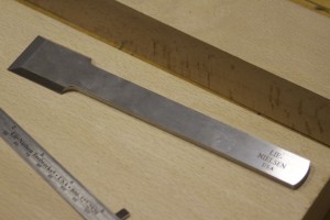
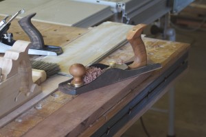
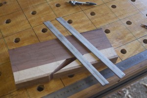
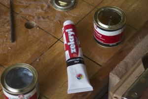
The third plane I prioritised to build was a shoulder plane. As per usual I decided to use a Lie-Nielsen blade in the form of their Large Shoulder Plane replacement blade. As you can see in the pictures below it is a blade that is designed to be used bevel up, given the bevels on the sides of the top of the bit end. I did not really grasp this until it was pointed out to me by Deneb Puchalski from Lie-Nielsen. I actually planed to bed the blade at 50-55º and use it bevel down. He advised me to consider a much lower bedding angle while using the blade bevel up.

I then started thinking of a way to change the design quite radically from the examples I found in my research. You will have to wait and see how it turns out as I myself still does not know exactly what the final design will look like. I will again (similar to what I did with the Scrub Plane) write this post as I progress with the project.

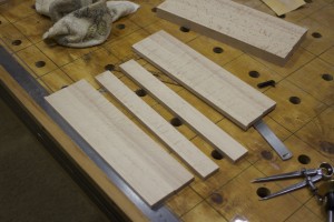
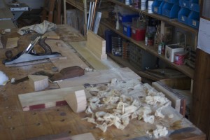
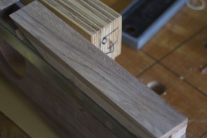
In the pictures below you can see the beech I used for the project and the Lie-Nielsen blade.

IMG_7476IMG_7477

As with the other planes I have built so far I had to laminate in order to get the size stock required. I laminated it in this particular orientation to ensure that I have the grain running in the direction recommended by the guys from Old Street Tools. I can really recommend their articles (which is available for free download from their site) on plane building. You will find the the link to their site on the library page of this site.

IMG_7478IMG_7479

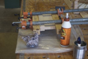
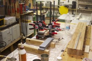
The lamination process. You will notice the use of my glue roller. I wrote a separate post on how I made this tool, which you will find under the category “Hand tools”
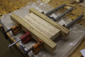
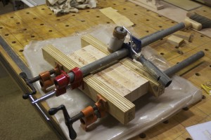
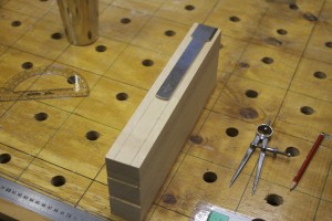
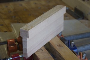
IMG_7480IMG_7481IMG_7482

The beech blank.

IMG_7484IMG_7485IMG_7486

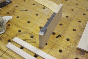
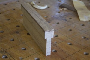
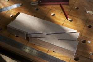
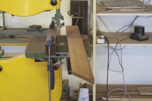
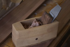
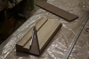
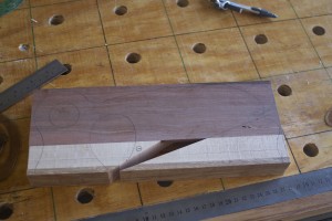
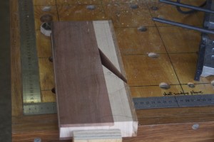
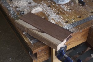
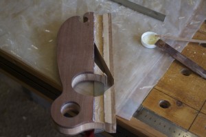
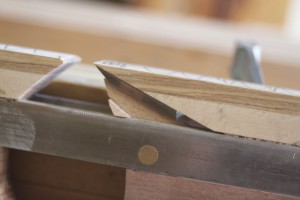
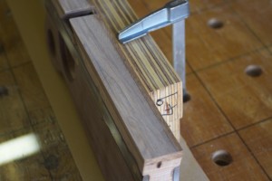
I used the actual blade to mark out the next step of cutting away the sides …

IMG_7487

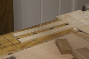
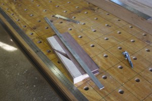
… as so. In the last of the three pictures you can see the strips I ripped off the sides, which were then glued back on the centre piece.

IMG_7489IMG_7490IMG_7491

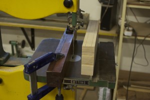
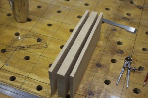
Before glueing the strips back I first fed the inside to the thicknesser to get it down to about 2 mm wider than the tang of the blade.

IMG_7492IMG_7493

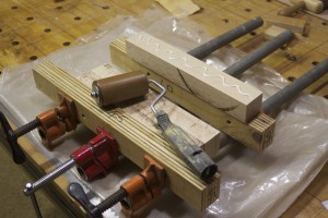
The strips were then hand planed to improve the contact during glueing.
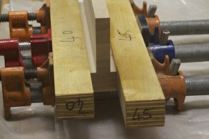
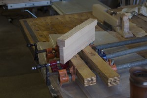
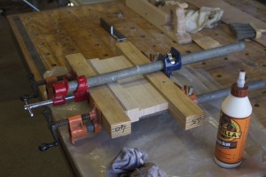
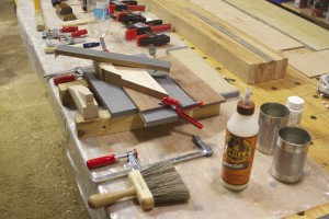
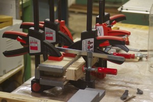
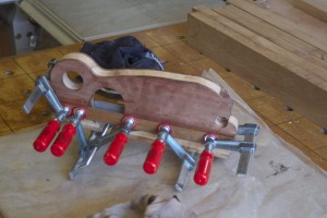
IMG_7494IMG_7495

Dry-fit and glue.

IMG_7496IMG_7497IMG_7498IMG_7499


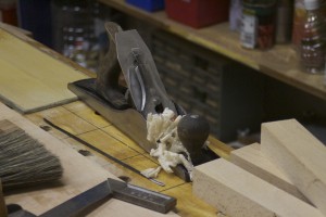
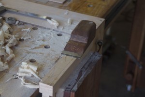
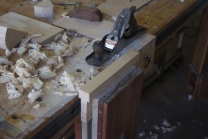
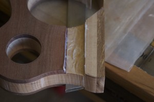
Here you can see how I removed the hardened glue with my shop-made flush plane before hand planing the sole in preparation for the glueing on of the ysterhout sole.

IMG_7503IMG_7504IMG_7505IMG_7506IMG_7507IMG_7507IMG_7508IMG_7509IMG_7510IMG_7511

Glueing on the ysterhout sole.

IMG_7513IMG_7514IMG_7516

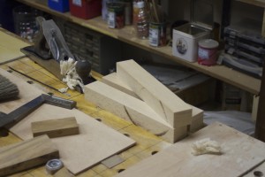
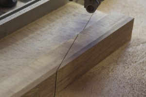
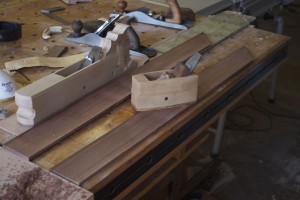
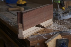
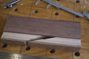
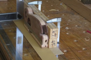
I then used my bandsaw Mitre-sled to cut a 20 º bedding angle for the blade and 12º space for the wedge.

IMG_7562IMG_7563IMG_7574IMG_7576IMG_7577IMG_7578IMG_7575

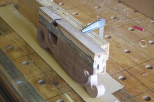
Up until this stage the design I was aiming for looked like the one below …

Shoulder plane design

… but I realised that the small triangular area on the “bedding piece” available as a glueing surface for the kershout sides (still to be made), would not be adequate. I therefore dropped the project and continued with the four other planes (Jack, Fore, Smoothing planes and a jointer) I started working on.

IMG_7579

1/10/2013

During a trip to Cape Town recently to go and what the Springboks butcher the Ozzies, I had some time to think on the plane (that is thinking on the airplane about the shoulder plane) and came up with an idea of how to hopefully make this plane work. As I am writing this I still have no idea if it would work as it entails quite a few tasks that I have never attempted before.

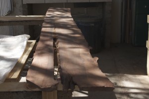
Anyway, I got back on the horse and took some beautiful kershout from this massive board. A Kershout tree of this size would have been between 700 – 1000 years old if my friend who studied these things knows anything.

IMG_7564IMG_7565IMG_7566IMG_7567IMG_7568

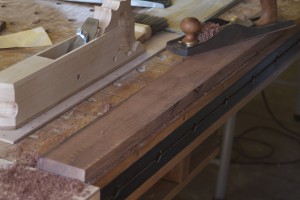
I re-sawed the piece on the bandsaw and tidied it up with the thicknesser and hand planes.

IMG_7569IMG_7570IMG_7571

Here you can see my delightful petite smoothing plane in action. I wrote an entire post on how I built it a few months ago (http://www.jenesaisquoiwoodworking.com/petite-wooden-smoothing-plane/)

IMG_7572IMG_7573

The plane was then glued together. In the first picture below you can see an unpolished piece of stainless steel, which is integral to the success (hopefully at this stage) of my new idea.

IMG_8068IMG_8069IMG_8070IMG_8071


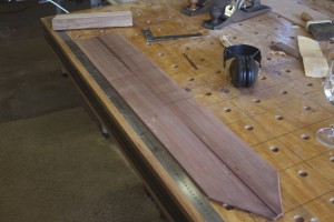
7/10/2013 – I released the plane from the clamps on Friday afternoon and spent an hour playing around with various shapes and designs based on an idea I had. Finally I came up with the design as drawn on the blank before heading down to our Barbie area to light a fire and drink a few cold beverages.

IMG_8072

On Saturday morning I started to shape the plane in order to be able to epoxy these strips of stainless steel in place so that it could set well overnight.

IMG_8073IMG_8074

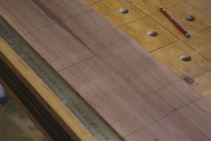
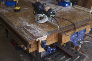
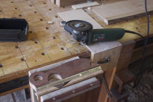
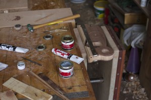
You can see how I made a few test cuts in a scrap piece of plywood to ensure the absolute correct depth of cut for the dado meant to accept the stainless steel. I used my removable pipe-clamp-end-vise to keep the plane in position for cutting the dado.

IMG_8078IMG_8079IMG_8080IMG_8081IMG_8082

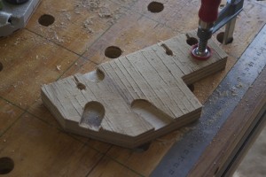
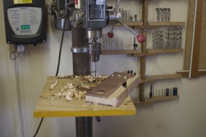
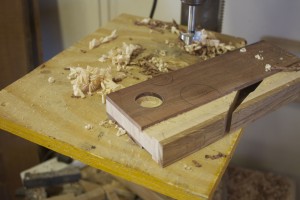
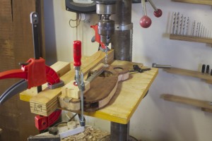
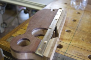
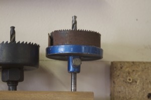
The two dados meant to accept the two stales steel bars is clearly visible in the first two pictures. I then proceeded to shape the rest of the plane by drilling out certain areas an using the bandsaw for the rest.

IMG_8085IMG_8086IMG_8087IMG_8089IMG_8088

The next step was to epoxy the stainless steel into place.

IMG_8091IMG_8092IMG_8094IMG_8096IMG_8095IMG_8097IMG_8098IMG_8099

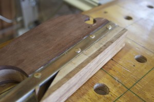
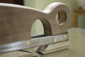
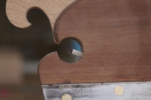
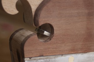
The next day I drilled out six holes through the stainless steel from side to side. These holes were 6 mm in diameter with the entrance chamfered slightly, as you can see. I made six pins out of 6 mm brass rod that was about 5 mm longer than the width of the plane and whacked it through the holes with equal amounts protruding at each end.

IMG_8110IMG_8112IMG_8113IMG_8114IMG_8117IMG_8118

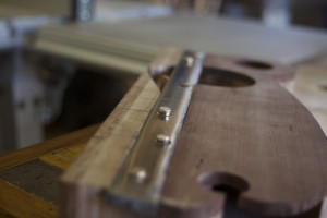
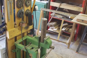
I used the setup below to rest one of the protruding ends on while whacking the other with a hammer until the brass moved into the chamfered area and fixing the stainless steel into this position for ever.

IMG_8119IMG_8120

As you can see in the pictures below, I then removed the untidy excess metal and polished it as best as I can given my lack of metal working tools and skills.

IMG_8121IMG_8122IMG_8123IMG_8124

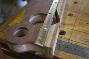
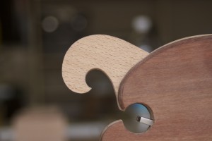
Then came the long hard slog of shaping the edges of the plane using a block plane, a spokeshave, and several files.

IMG_8126IMG_8127IMG_8128IMG_8129IMG_8130

Sides were tidied up with my shop made proletarian sanding contrivances.

IMG_8131IMG_8132

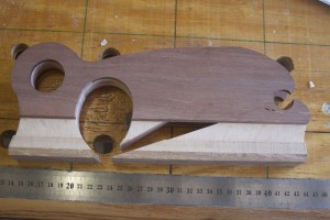
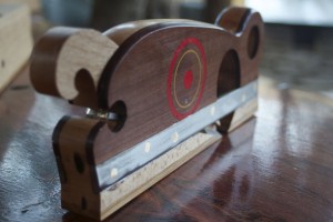
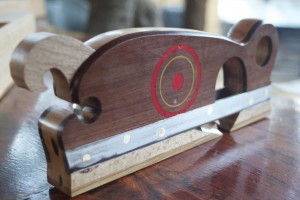
At present the plane looks like this. Next I have to make the wedge and am considering to try some decorative coloured epoxy inlays, but let’s see what happens.

IMG_8133IMG_8134IMG_8135


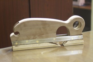
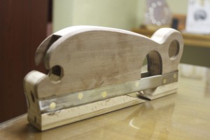
13/10/13 – On Friday afternoon I quickly fashioned this wedge out of beech.

IMG_8136-2

On Saturday I changed the shape ever so slightly as you can see here. The blade will be set by a special plane hammer with a delicate neck, which I still have to build.

IMG_8137-2IMG_8138-2IMG_8139-2IMG_8141-2IMG_8142


IMG_8143-2

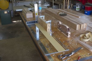
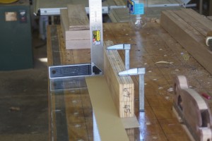
The next step was to ensure that the sole of the plane is 100% square with the left cheek. As a right-hander I would use the plane predominantly with the left cheek as reference surface. I used the setup as shown to sand the sole square.

IMG_8145-2IMG_8146-2IMG_8147-2IMG_8148-2IMG_8149-2IMG_8150-2IMG_8151-2IMG_8152-2IMG_8153-2IMG_8154-2

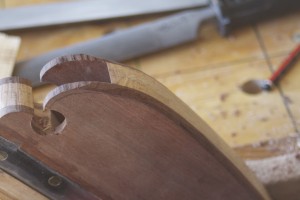
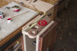
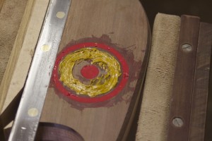
As discussed in one of the “My journey” posts, I am using this tool building phase to try out and practice techniques that might come in handy when I start building furniture. Here I thought of trying-out coloured epoxy inlaying to add some je ne sais quoi to the shoulder plane. I used the drill bit pictured to create the grooves and tidied it up with a carving tool.

IMG_8155-2IMG_8156-2IMG_8157-2

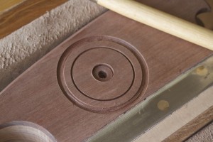
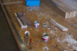
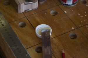
As you can see, I mixed some epoxy with acrylic paint …

IMG_8158-2IMG_8161-2

… and used small scrap bits of wood as spatulas to work the mixture into the grooves. After a few hours I used my shop made flush plane to cut most of the excess away before the epoxy became too hard. It is a shlep to sand it away once it becomes rocklike.

IMG_8160IMG_8162IMG_8163-2IMG_8164-2IMG_8165-2IMG_8166-2

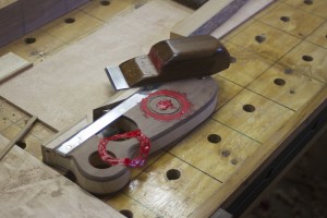
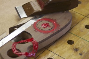
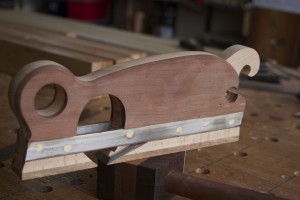
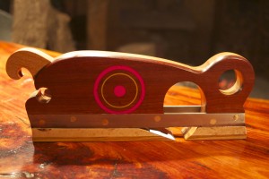
I then used my proletarian sanding contrivances to sand away the last little bit of epoxy and started the finishing process as shown.

IMG_8167-2IMG_8173-2

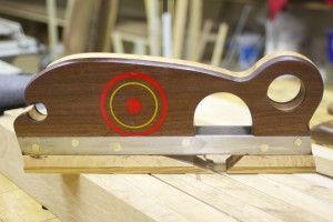
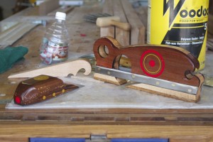
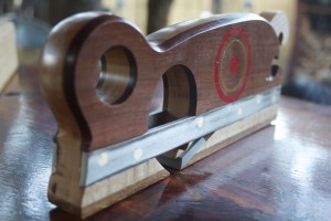
Here are a few pictures of the finished shoulder plane. Now I only have to sharpen the blade and Bob’s your uncle. The blade is bedded at 20º with a 25º primary bevel. I am planning to hone and polish a small secondary bevel at 28º, producing a 48º effective angle of attack.

IMG_8193-2IMG_8194-2IMG_8195-2IMG_8196-2IMG_8268IMG_8332IMG_8301IMG_8353