All posts by Gerhard Marx

Psychiatrist and Woodworker

Scissor rehab

22/4/2014

This is the pair of scissors that came with my father’s tools. Until recently it could not even cut toilet paper. It is however good German steel and made during the time when people still cared about quality. Therefore I decided to rehabilitate it by sharpening and repainting it.

IMG_0201

The bits of old paint disappeared with the help of paint stripper.

IMG_0204

I did some research on how to properly sharpen scissors in the electronic version of the book pictured below. I can really recommend it for all sharpening purposes.

sharp

A new coat of paint …

IMG_0214

… and Bob’s your Uncle.

IMG_0227

My 18th Century Workbench in progress 4

20/8/2014 I realised over the past week that this post is becoming far too big and therefore a major mission to download. That is why I broke it up into lots of smaller posts that should be easier to download and follow. Simply click on the “Building my benches” category and follow the numbers. I have also changed the name of the post to “My 18th Century Workbench in progress”.

9/4/2014

I am sure you are as sick of lamination discussions as I am of perpetrating them. You will therefore be relieved to know that we are moving onto the next phase of this epic journey, entitled “Joinery and Armament”. It will be the first time in my woodworking career that I take on such ginormous joinery and as you might expect by now, it will be an exercise in overdoing it.

As much as I want to move on to this phase, I have to warn you (and myself, mind you) that there are quite a bit of squaring up left to do, on the laminated parts (painstakingly by means of hand planes predominantly), which I will add to the previous post as I get it done.

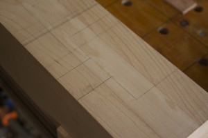
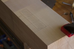
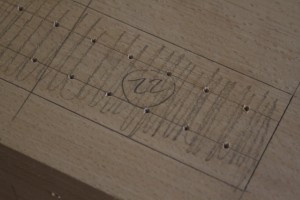
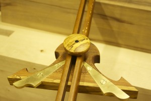
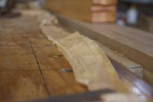
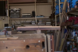
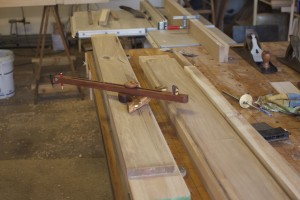
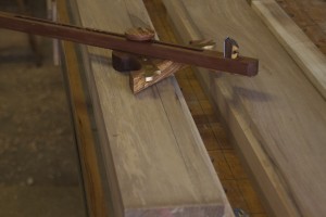
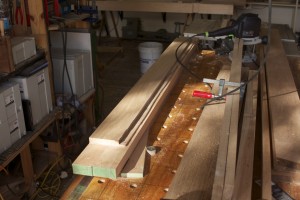
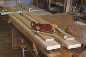
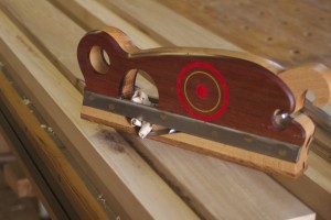
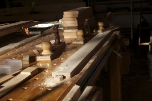
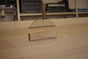
Sunday evening after packing everything away in the shop I sat down with a glass of vino and played around with some ideas for this bench’s sliding deadman. The bench is very traditional in most aspects, so I wanted to give it at least some fresh twist (pun intended). Otherwise known as je ne sais quoi. This is what I came up with.

Sliding DeadmanSliding Deadman 2


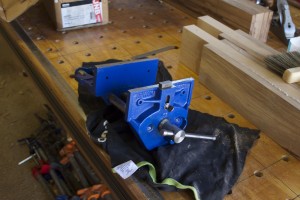
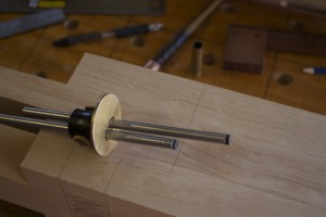
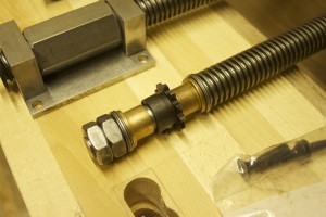
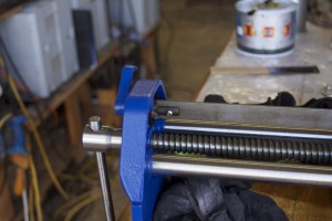
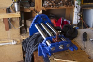
A few weeks ago, my main man, Aldan, at Windhoek Tool Centre sourced this 175 mm Irwin Record quick-release vise for me. It is meant to become the end vise of my bench. After all the chopping and changing between different options for the tail vise, the economy prevailed and I settled on a quick-release vise. Unfortunately I only made friends with Patrick Leach a few weeks after I bought it, because I am sure he could have found me a much better made vintage model. You have to live and learn, I guess. I am however considering to ‘Paint it Black’ , (à la the Rolling Stones), as I really do not like the blue. It is a je ne sais quoi thing, I think.

IMG_0065IMG_0066


8/4/2014

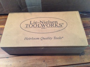
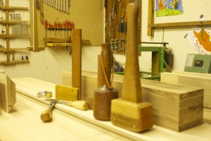
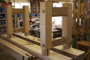
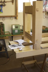
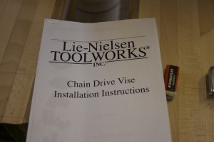
Today I received the long-awaited Lie-Nielsen hardware for my bench and two new tools that will make it so much easier to build it. As you will see the shipment includes a large closed throat router plane, a large tongue and grove plane, a single screw vise (for the leg vise) and a chain drive twin screw vise (for the twin screw face vise with 24″ between screws). As you might remember, I am planning to put a twin screw vise in one of the face vise positions (as per the classic Holtzapffel design) and a leg vise in the other, as my bench will be accessible from both sides (rather than being braced against a wall). You will have to be patient in order to see the hardware liberated from the safety of it’s packaging. For now it will stay snug in it’s LN travel gear.

IMG_0025IMG_0026IMG_0027IMG_0028IMG_0029IMG_0030IMG_0031IMG_0032IMG_0033IMG_0034IMG_0035IMG_0036IMG_0037IMG_0038


14/4/2014

During the latter stages of last week I consulted Deneb Puchalski who is my go-to man when I need solid advise. I realised over the past few weeks, since reading up on the characteristics of the PVA wood glue that is readily available to me (a company by the name of Alcolin), that it will be impossible to assemble and clamp the whole bench in one go with the short open-time of these products. I therefore started thinking of using slow-setting epoxy for this task. As far as I can gather it will be at least as strong as the PVA type white and yellow glue (which is anyway quite a bit stronger than the wood), and might have an edge as far as shock resistance. Deneb advised me to consider Tite Bond III (which is a real mission to access in Namibia) or slow-setting epoxy.

The next step was to try and find a good quality epoxy for the job. I spoke to my friend Sigmund Mengerssen who told me about IBS. They stock ABE products. I spoke to a gentlemen by the name of Wolfgang who seemed to know what he was talking about. I explained the whole situation and he recommended OBE’s Epidermix 372 Epoxy Adhesive. It turns out it is the exact same product as what I have been using in small amounts for the past few years, especially for the hand tools I’ve built. This time I bought a bigger supply (1 liter) than the 90 ml I used before. Wolfgang advised me that I will have around 2 hours of assembly time with this product and I gather from the data sheet that it takes 6 hours to become ‘touch dry’, 24 hours to set for ‘practical use’ and a week until it is ‘fully cured’.

IMG_0039

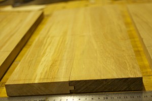
I also sent an e-mail to Attila Hoth of Southern Wood Trading requesting two beech boards in the order of 50 x 130 x 2700 that is quarter sawn and not too recent immigrants to this fair land. This should hopefully become the leg vise chop, twin screw chop and two sliding deadmans (or should that be deadmen??).

20/4/2014

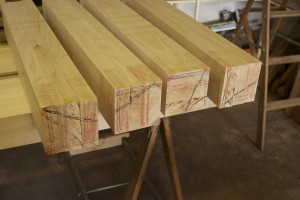
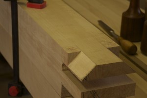
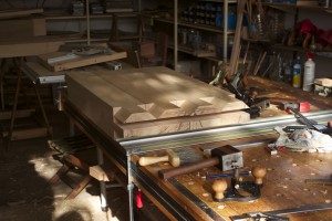
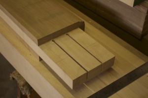
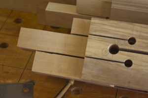
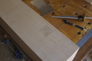
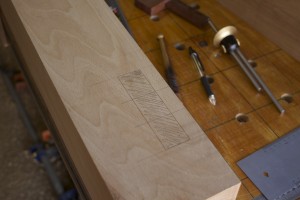
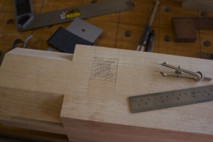
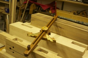
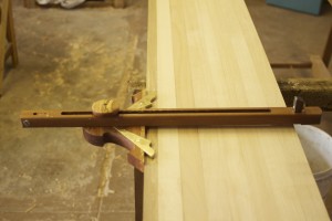
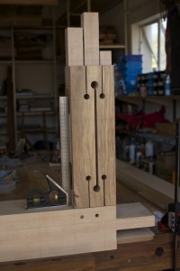
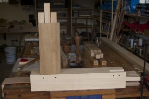
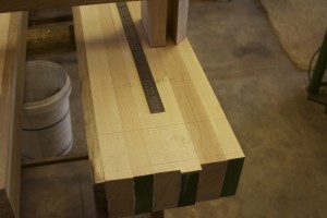
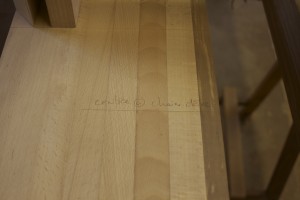
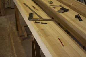
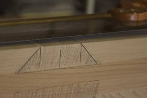
Finally I got stuck into the joinery phase during the Easter weekend. I took the age-old advise of “measure twice, cut once” quite serious and therefore spent a good bit of time on this particular task before cutting the male parts of the sliding dovetail and mortise at the top of the legs. You can see the carpenters triangle which will help me to locate the legs to their correct positions after they inevitably get mixed up during all the joinery processes.

IMG_0229IMG_0230IMG_0231


I used the exact measurements for the sliding dovetail and mortise, which Chris Schwarz deducted from the plate in Andre Roubo’s landmark five-volume 18th century book  “L’Art Du Menuisier”. As I mentioned earlier in this opus, the two books on bench building by Chris is definitely worth buying if you are contemplating a project like this. The plate below I found on the Lost Art Press blog site. You will notice the leg with the mentioned joinery in the bottom left corner (first picture).

plate11_fullPlate 11_bench

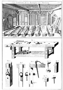
Speaking of Chris Schwarz, he advocates that one should, and I quote:

“You don’t need to invent anything, patent anything or manufacture anything to create a workbench that’s better than what’s lurking in the aisles of many stores today. Workbench designs evolved into their highest form more than 300 years ago. And they are just waiting to be rediscovered by anyone who can under- stand that though things are always changing, that doesn’t mean they are always improving.”

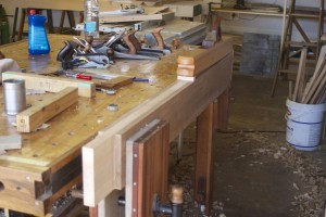
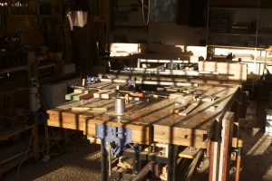
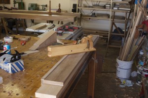
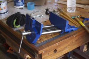
Despite his advice, I designed my assembly table with the quick release vise in the middle of the end of it with a removable pipe clamp on either side. The pictures below will hopefully show that this design has at least some merit, during the few years that the assembly table doubled up as a workbench.

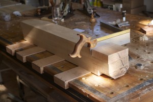
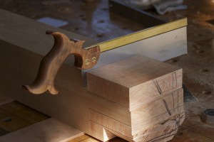
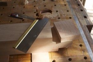
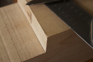
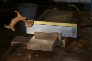
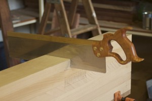
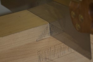
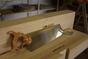
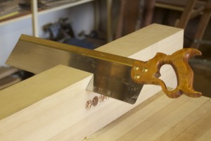
Anyway, after a few test/warm-up cuts in a scrap piece of Rhodesian Teak, I found a very first task for my 16″ Lie-Nielsen tenon saw. The effective cutting depth of the saw was found wanting, as you can see, but I guess it is unlikely that I would ever cut tenons of this size again.

IMG_0293IMG_0294IMG_0232IMG_0233IMG_0234IMG_0235IMG_0236

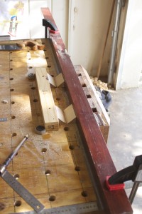
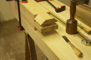
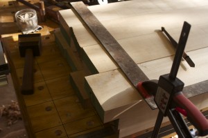
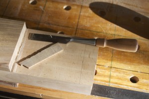
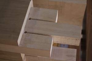
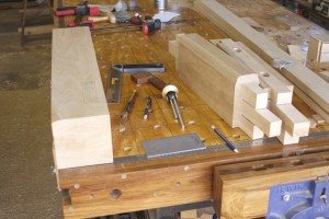
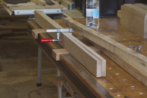
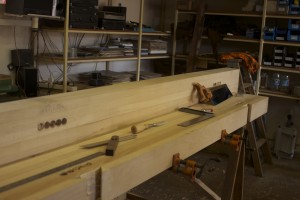
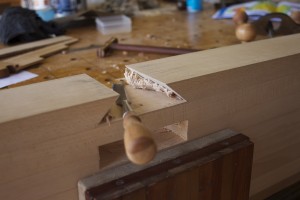
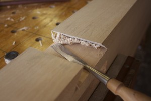
To deal to the untouched waste left over on the sliding dovetail tenon, I devised the setup below. A combination of bench dog’s, clamps and handy beams created a very stable slot for the leg to rest while presenting it’s edge for me to go mental on it with my Lie-Nielsen carcass saw. Two kerfs in each of the triangular pieces of waste would make it much easier to later chop it away with a chisel.

IMG_0246IMG_0237IMG_0238IMG_0239IMG_0241IMG_0242

Finally, some proper woodwork.

IMG_0243IMG_0244IMG_0245

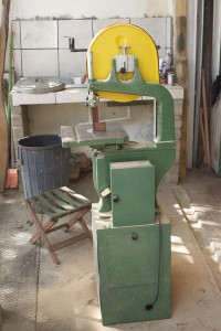
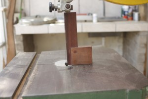
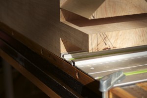
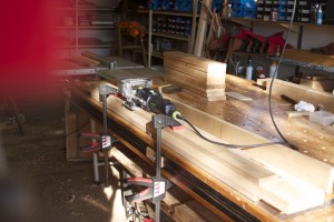
Next I had to set up my bandsaw to make accurate square cuts. As you can see in the second picture, it somehow found it’s way significantly out of square since the previous tune-up. After sorting that out I cut the necessary kerfs, to create the tenon and the back of the dovetail.

IMG_0248IMG_0247IMG_0249

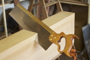
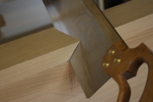
In order to cut the shoulder at the back of the leg, I found a very first job for the set of bench hooks I made more than a year ago. You can see how they performed admirably in fixing the leg while I used the carcass saw to cut the mentioned shoulder.

IMG_0250IMG_0251IMG_0252IMG_0253IMG_0254IMG_0255

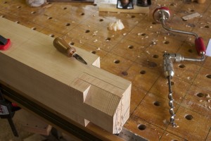
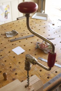
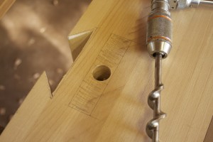
I just realised that there are a lot of firsts (in terms of tools being used for the first time) in this phase so far. Here you can see how I used my shop made so called Brace Bit Birdcage Awl

(http://www.jenesaisquoiwoodworking.com/brace-bit-birdcage-awl-also-known-as-bbba/)

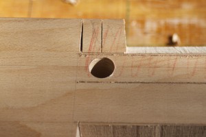
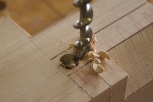
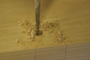
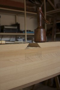
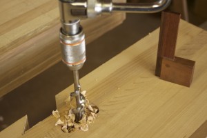
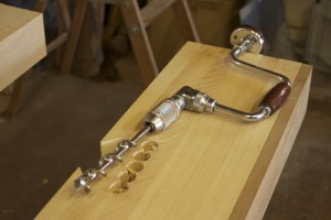
for the first time to make holes were the Irwin Auger bit can take hold. I decided to use the brace and bit to drill out waste before attacking the area between the two tenons with a mortise chisel. I first sharpened the bit carefully, as it probably last saw action during the Great War. It was actually surprising to see how enthusiastically it munched away the mentioned waste.

IMG_0306IMG_0307IMG_0256IMG_0257IMG_0258IMG_0259IMG_0260IMG_0261IMG_0309IMG_0308

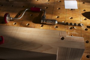
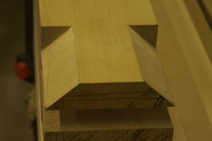
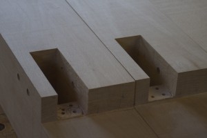
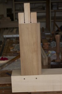
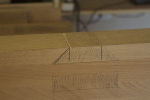
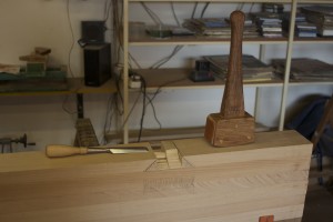
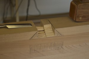
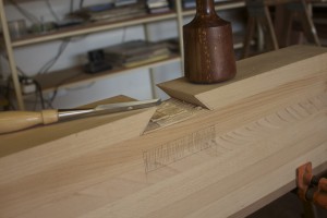
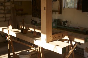
Speaking of firsts, this next task also became the first ever performed on my bench-to-be’s top. I clamped the legs to the top where it was resting on my Darwinian saw horses. The pictures show the sequence of destruction I followed to get rid of the waste.

IMG_0267IMG_0310IMG_0311IMG_0312IMG_0313IMG_0315IMG_0317IMG_0318IMG_0295IMG_0296IMG_0297IMG_0298

A quick change in clamping position and I could go ape-shit on the triangular section of waste left over at the bottom of the sliding dovetail.

IMG_0301IMG_0302IMG_0303IMG_0304

… x 4 and so far so good …

IMG_0339IMG_0340


28/4/2014

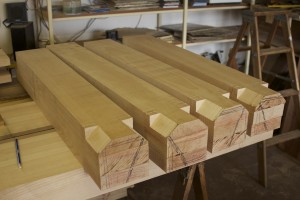
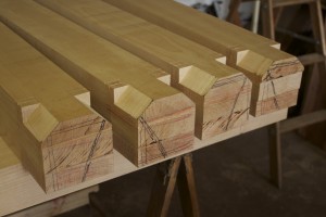
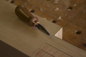
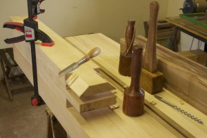
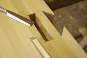
After removing the bulk of the waste from the male parts of the joinery, I used my shop made marking knife to mark out the exact lines to work to. In the pictures you can see how I used a whole range of tools to do the precise cleanup work.

IMG_0376IMG_0377IMG_0378IMG_0379IMG_0380IMG_0381IMG_0383IMG_0387IMG_0388IMG_0389IMG_0392IMG_0393IMG_0394IMG_0396IMG_0398IMG_0399IMG_0401


In these pictures you can see how I used a very simple jig to get the shoulders of the tenon exactly 90º.

IMG_0402IMG_0403

Again the assembly table came in handy to set up the leg for some precision pairing.

IMG_0404IMG_0405

I then used the setup as illustrated below (referencing off the shoulder lines of all the legs) to identify the final length of the legs. The bench will be 82,5cm high (32.48″). Replaced the carpenter’s triangle at the bottom of the the legs after chopping off the waste with the bandsaw.

IMG_0406IMG_0407IMG_0409IMG_0410IMG_0411IMG_0414IMG_0413IMG_0412


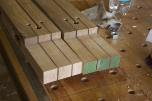
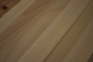
Here I took on another arduous planing task by preparing the two reference surfaces of the two sets of stretchers. After lots of deliberation, rereading Chris Schwarz’s book and even the translation of the first chapter Andre Roubo’s 18th century book  “L’Art Du Menuisier” (on the Lost Art website), I decided that my stretchers might be a bit of an overkill at 170 mm (about 6½”). Therefore I shaved off 40 mm to bring it back to 130 mm. The final product will in the end be back at 150 mm after adding some Witpeer to make the stretcher appear as if it consists of only Witpeer, but we will get back to that later.

IMG_0415IMG_0416IMG_0417IMG_0426IMG_0430IMG_0431

30/4/2014

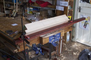
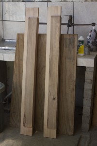
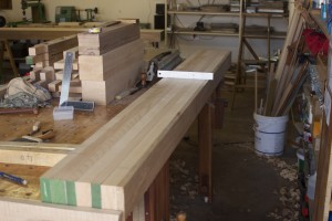
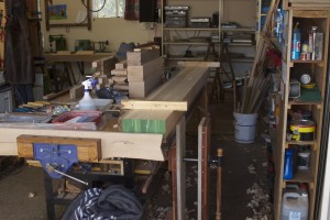
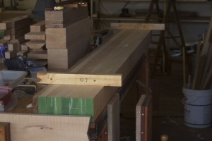
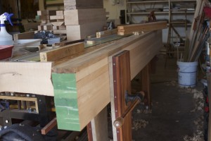
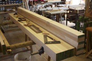
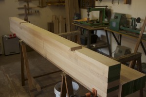
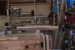
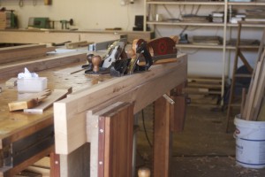
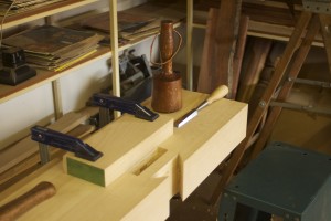
Attila Hoth dropped off the three beech boards I requested tonight. As we are about to abandon Windhoek for a 10 day migration to our Fishing Camp on the mighty Okavango River for a spot of Tiger fishing, I simply clamped them to my assembly table to stay honest while settling into my shop’s particular ambiance.

Tweede hout

18/5/2014

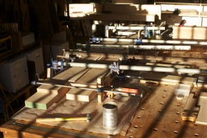
Finally I was able to progress with the joinery this weekend after our African adventure. First on the to-do list was to use the actual leg to mark out the shoulder lines of the short stretchers and two aprons. The work-holding ability of my shop made assembly table made it possible to set up a frame in order to mark out each set exactly the same. You will notice that I referenced the vertical position of the legs off the shoulders of the through mortises. For the width of the bench I finally settled on a fraction over 25″.

IMG_0875IMG_0876IMG_0877IMG_0878IMG_0879IMG_0881IMG_0882IMG_0883

In order to locate the short stretchers, I made two batons of 3 mm plywood that are exactly the same length and used that to reference off the bottom of aprons, which were in turn set up flush with the tenon shoulders. With all the parts firmly clamped into position as you can see in the last picture, I used a 0.3 mm mechanical pencil to mark out the exact shoulder lines on the apron and stretcher. Then it was simply a question of repeating the process on the second set of parts.

IMG_0884IMG_0885IMG_0886IMG_0887IMG_0888IMG_0889

The pencil lines generated during the above activity was then used to mark out the rest of the shoulder lines with a marking knife, while taking care to always reference off a face side or face edge. You will see that I have started using the technique/scribble taught by Robert Wearing to indicate the two face sides.

IMG_0890IMG_0891IMG_0892IMG_0894

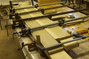
At this point I realised that I really should add the final part of the stretcher before cutting the shoulders. I decided a while ago already to laminate yet another strip to make it appear as if the stretcher is solid Witpeer. Therefore I had to mill another feral board into sophisticated strips for the top of all four stretchers and laminated it onto the already ominous looking (3″ x 5½ before the strips were added) short stretchers.

IMG_0895IMG_0896IMG_0897IMG_0898IMG_0902IMG_0914IMG_0915

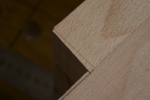
In the meantime I started sawing the shoulders of the aprons and made a point of trying to saw to the line. I did not want to remove as much material with the chisel as what I had to do on the through mortises at the top of the legs. Again I used one of Robert Wearings tricks to get the saw started perfectly. He describes how you used a chisel to pair a shallow ditch (pictured) on the waste side of the shoulder line to guide you saw. Once the shoulders were cut it was piece of pie to chop the waste away with a chisel.

IMG_0899IMG_0900IMG_0901

The big frustration of the weekend was when I realised that I still needed to cobble together a fence for the #78 Stanley rabbet plane (that I am in the process of restoring into a working tool) before I can use it to hand-cut mouldings with it. That forced me to design and fashion this Ferrari-esque contrivance …

IMG_0919IMG_0920

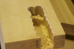
… which despite it’s dilapidated appearance, performed admirably in tandem with a small block plane and a card scraper in producing these hand-cut mouldings . You will notice that these mouldings were designed to hide the lamination. Together with a good colour match it makes it impossible to notice the lamination, once the stretcher’s shoulders are glued into position between the legs.

IMG_0921IMG_0922IMG_0923IMG_0924IMG_0925IMG_0926IMG_0927IMG_0928IMG_0929IMG_0930IMG_0931IMG_0932IMG_0933

However, that took most of the day so I ended up feeling a bit despondent about the weekends progress.

25/5/2014

I managed to chip away at preparing the aprons a little bit each night during the week. Here you can see how I squared up the shoulders first by chopping down using the prop to improve accuracy and finally some horizontal pairing to get it perfect.

IMG_0934IMG_0935IMG_0936IMG_0937IMG_0939IMG_0940IMG_0941IMG_0942

Then I moved on to a plan I dreamt up to deal with wood movement. Windhoek has some of the most challenging seasonal changes in humidity of any location in this part of the world. In my shop the ambient humidity changed from 20-25% in winter to 75-80% during the rainy season last year. This means that the Equilibrium Moisture Content of the wood (which average around 6%) can fluctuate between 1-11%. This represents a major challenge when building a bench that needs to stay as flat as possible. This is the main reason why I designed my bench with a split top to allow the two parts (which will be fixed to the legs by means of the Roubo through tenon and sliding dovetail joints) to move into the space between them, rather than trying to pull the leg-apron joints apart. Please note the elongated hole for the 20 mm threaded rod that will fix the top to the apron, which is meant to allow for the mentioned horizontal wood movement.

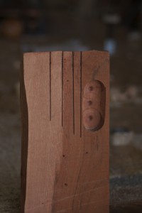
In order to deal with the vertical movement of the top, I use the following strategies: 1) chose quarter sawn stock for the aprons, 2) cut relief gaps (for a lack of a better term) into the aprons. The holes drilled into the aprons in the pictures below, was the start of that process. Hopefully the pictures will do a better job of explaining.

IMG_0943IMG_0944IMG_0945IMG_0946IMG_0947IMG_0948IMG_0949IMG_0951IMG_0953IMG_0954IMG_0955IMG_0956IMG_0958IMG_0959IMG_0960IMG_0961IMG_0962IMG_0964


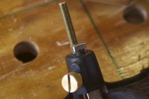
Here I did a quick check to make sure the 20 mm threaded rod is able to move freely in the elongated slot.

IMG_0965IMG_0966

I then grabbed the router to remove an area to allow the bolt to be countersunk below the bottom surface of the apron. This is important to ensure that a clamp can still find a nice flat surface in future, then using F-style clamps through the split top.

IMG_0967IMG_0968IMG_0969IMG_0970IMG_0971IMG_0972IMG_0973IMG_0974

The router also assisted with the initial 20 mm (depth) or so, of this 6 mm (width) relieve groove, before I took to it with the drill press, a chisel and finally a bed float.

IMG_0975IMG_0976IMG_0977IMG_0978IMG_0979IMG_0980IMG_0981IMG_0982IMG_0983IMG_0986IMG_1002IMG_1003IMG_1004


I used the bandsaw to cut two 3 mm wide relieve grooves in each tenon which extends and overlaps with the aforementioned relieve groove. This will hopefully mean that the tenon (which is about 115 mm (about 4½”) wide) will be able to expand without destructing the joint and for the apron to have minimal effect on the top when it inevitably moves throughout the year.

IMG_0987IMG_0988IMG_0989IMG_0990


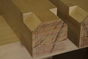
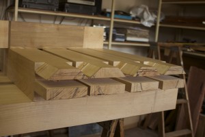
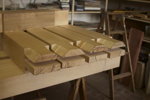
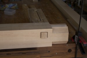
The three ‘fingers of each tenon were then cut to length. You will notice that there are a short haunch at the top (which stops short of the main tenon at the top of the leg in order not to weaken it) a through tenon in the middle (which will be wedged at the front of the leg) and a normal tenon at the bottom (which stops about 1″ short of the front of the leg). Both middle and bottom tenons will be pinned with a custom made 10 mm Assegaai dowel.

IMG_0991IMG_0992IMG_0993


Then I turned my attention to the end (short) stretchers. I followed the same process as with the aprons. I only difference was that I found it a bit tough going with the carcass saw cutting the shoulders so I tried the tenon saw and it worked like a charm. The teeth of the tenon saw are set for ripping but I can honestly say that it worked as well as the carcass saw, only better because of the bigger teeth and extra weight and length it brought to the party.

IMG_0994IMG_0995IMG_0996IMG_0997


The waste was removed by chisel.

IMG_0998IMG_0999IMG_1000IMG_1001IMG_1005IMG_1006

The shoulders were squared up by chopping followed by horisontal pairing.

IMG_1008IMG_1009IMG_1010


Seeing that it is insignificant whether the stretchers move slightly, I only cut the relieve grooves in the tenons to protect the integrity of the join.

IMG_1012IMG_1011IMG_1013IMG_1014IMG_1016


As with the aprons the three fingers of each tenon were cut to different lengths. In this case the two outside tenons were shortened and the one in the centre were left long to become a through tenon to be wedged. Both the outside tenons will be pinned too. I plan to do the opposite with the side stretchers where the outside fingers will be through tenons and the central one shortened.

IMG_1017IMG_1018


On to the female parts of these joints. I used the same setup as before to mark out exactly where to cut the mortises using the actual aprons and stretchers. Again the position of the legs were referenced off the inside shoulders of the through tenon at the top of the legs (see first picture).

IMG_1019IMG_1020IMG_1021IMG_1022IMG_1023IMG_1024IMG_1025IMG_1026IMG_1027IMG_1028IMG_1029IMG_1031IMG_1032


2/6/2014

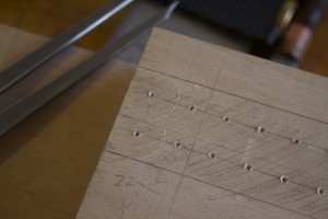
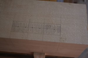
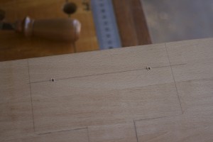
Once again I took the measuring out quite serious spending most of a Saturday morning to measure out exactly were the mortises should be cut in the legs. I made the effort to measure the shoulder of each specific tenon at the top and bottom (of the in and outside) with the Veritas marking gauge (pictured) and transferring that to the leg to ensure that I get as close as possible to perfect. The four reference points generated in this way were then used to cut the long sides of the rectangle by means of a marking knife and straight edge. The short sides were cut using a square guided by the pencil marks of the actual tenons on the leg as demonstrated in the previous set of photographs. You will notice that each mortise have a entrance side and a exit side.

IMG_1035IMG_1043IMG_1044IMG_1046IMG_1036IMG_1038IMG_1039IMG_1040IMG_1041IMG_1042

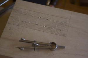
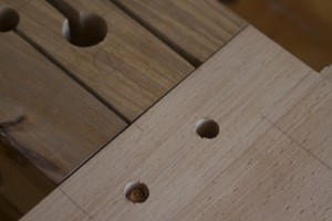
Since I recently realised how useful dividers can be in marking and laying out all sorts of measurements in woodwork, I used it to establish which size drill bits would work best for the removal of the waste from these mortise. It also came in very handy in marking out where to drill the holes. You will notice how I marked out the location of each assault on the mortise, as well as writing the diameter (in millimeters) of the spade/Forstner bit to be used in pencil.

IMG_1047IMG_1048IMG_1050IMG_1049IMG_1051IMG_1052IMG_1053IMG_1054

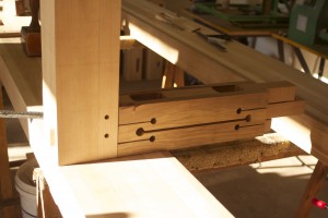
All the tenons will be pinned in two places. Here you can see how I marked out where to drill the holes for the 10 mm custom made Assegaai dowels. These dowels are still to be made. Please note that the holes for the long and short stretchers will be in the same plane, which is contrary to what is usually done. I decided to break this very sensible rule as the design of my tenons (for reasons of wood movement) does not allow enough room to have them in different planes while still being imbedded in a robust hunk of timber. You will see how I plan to overcome this particular challenge as we progress.

IMG_1045IMG_1046

IMG_1055IMG_1056IMG_1057IMG_1058IMG_1059IMG_1060


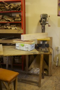
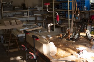
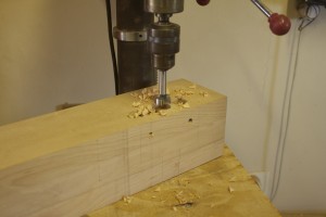
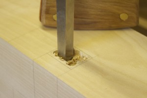
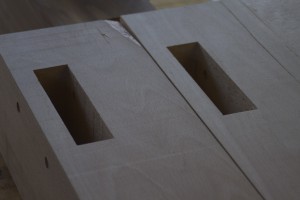
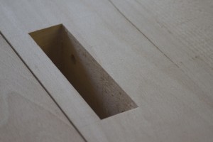
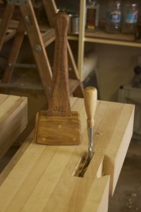
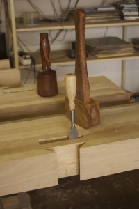
Here I started removing the bulk of the waste from the mortises on the drill press. It looks like a piece of pie, but it took ages, trust me.

IMG_1061IMG_1062IMG_1063IMG_1064IMG_1065IMG_1066IMG_1067IMG_1068

IMG_1069IMG_1070IMG_1117IMG_1118IMG_1119IMG_1120


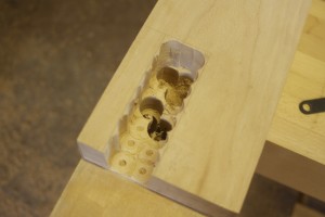
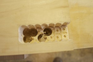
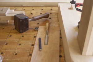
Then came the real elbow grease part of the job, removing the rest by means of a mortise chisel and a shop made mallet. Whack, whack, whack, whack, whack, whack, whack, whack, whack, whack, ……………………………………. (weeks later)………………………… whack, whack,whack,whack ………………….. (even more weeks later) …………. whack …… OK I am sure you get the picture.


IMG_1121IMG_1123IMG_1124IMG_1125IMG_1132IMG_1133

IMG_1134IMG_1135IMG_1136IMG_1137IMG_1138IMG_1139IMG_1140IMG_1141IMG_1142


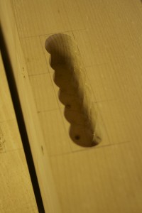
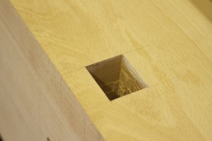
Some evidence that I really did do all that drilling and especially all that whacking.

IMG_1143IMG_1145IMG_1146


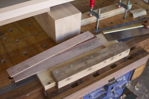
While all the whacking was going on I milled down the swarthout (which was laminated six weeks ago or so) destined for the cleat under the shelve between the stretchers, in order to take a well deserved break.

IMG_1161IMG_1162IMG_1163


….. and whack whack whack etc etc ……

IMG_1164IMG_1165IMG_1178IMG_1179


16/6/2014

At this point in time I took a break from all the mortising, to build a monster Panel Gauge. Look out for a post entitled “Makeshift Panel Gauge”, which is soon to be released. I need one for the next major hand planing war that is about to break out in the previously peaceful surroundings of my workshop. I need to flatten the edges of the two parts of the twin-top. They are too big to fit through my planer, so after flattening one edge I will need to use a panel gauge to mark out the opposing side and hand plane that parallel to the reference edge. The mortises below is only one step away from being finished.

IMG_1180IMG_1181IMG_1182IMG_1183


23/6/2014

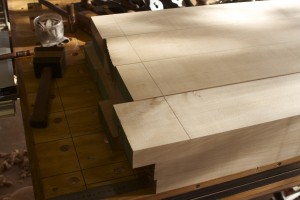
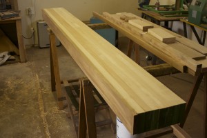
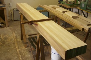
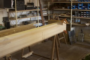
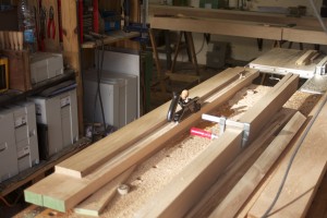
In the meantime I realised that I need to start squaring up the two beams of the twin top. As they are too wide to fit in my planer upright I will have to do that (planing to width) by hand planing. Once I get one edge square to the face side I will need a panel gauge to mark out the opposite side. Problem is, I do not have a panel gauge of that size. The idea was to build a makeshift panel gauge as I wanted to get onto the next step with the bench, but my tool design-OCD kicked in and it led to a protracted design and manufacturing hiatus. The end product of which is featured in the pictures below. I wrote a post on the process entitled “Makeshift Panel Gauge”.

IMG_1360IMG_1362

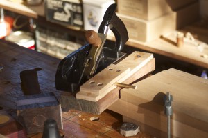
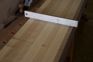
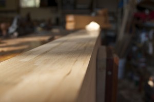
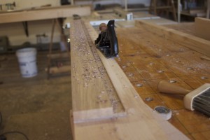
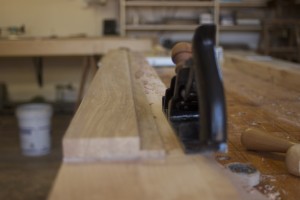
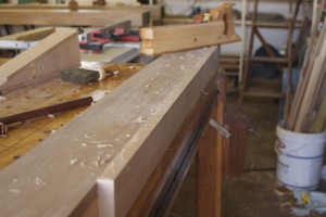
This past weekend the process of handplaning these monster beams started with a vengeance. I like starting off by hollowing out the face side ever so slightly. I used the short straight edge to check all along the length of the face side. If it does not pivot on the edges, it is not hollow yet.

IMG_1370IMG_1386IMG_1389IMG_1387IMG_1388


Next I check for wind using my truly makeshift winding sticks. This is why I start by hollowing out the face side from side to side, otherwise you get the wrong reading when using the winding sticks. If there is a bump at any point across the width, the winding stick can adopt one of two different positions. Once the winding sticks make contact with the face side’s edges only you get the true reading and can therefore proceed to fix the twist. In this case I had minimal work to do as I removed (by hand planing) most of the twist prior to feeding the beams to my planer about 6 weeks ago.

IMG_1371IMG_1372


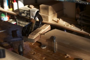
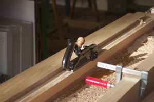
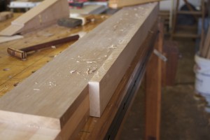
Once the face side was slightly hollow and twist free, I could square the face edge using the face side as reference. You can see how my shop made jointer came in very handy.

IMG_1373


Then I used my newly produced panel gauge to mark out the opposite edge to be parallel to the face edge.

IMG_1375IMG_1378IMG_1377IMG_1380IMG_1391IMG_1392IMG_1411


28/6/2014

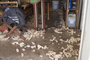
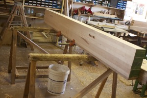
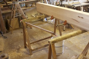
I went through the same motions with the other side of the top. You can see in some of the pictures what beautiful full length shavings I produced with my shop made jointer.

IMG_1419IMG_1420IMG_1421IMG_1422IMG_1423IMG_1418IMG_1440IMG_1441

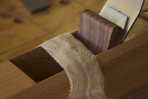
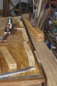
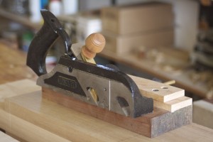
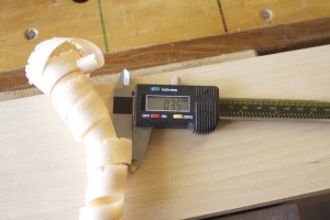
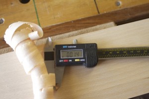
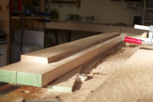
In order to remove the bulk of the material on the opposite edge, I first used my shop made scrub plane as a very aggressive fore plane (with the grain). You can see the shavings produced by the heavily cambered blade (3″ radius), measured 0.35 mm (0.014″) in thickness. It made short work of the waste that needed to be removed.

IMG_1442IMG_1443IMG_1458IMG_1459IMG_1460IMG_1462IMG_1463IMG_1464

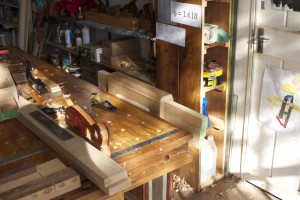
Again, just some evidence of all the heavy hand planing that I have been engaged in for the past few weeks.

IMG_1468IMG_1469IMG_1470

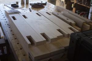
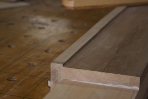
I finally returned to the mortises and tenons of the aprons and stretchers. It all needed some TLC to fit together perfectly. I used a float and a few chisels to do the fine tuning. I have to say that for a first attempt at such massive joints it all came together splendidly. You will notice the gaps at the top and bottom of the through tenon/mortise created to except wedges.

IMG_1474IMG_1475IMG_1476IMG_1471IMG_1472IMG_1473IMG_1477IMG_1478IMG_1479IMG_1480IMG_1481IMG_1482IMG_1483IMG_1484IMG_1487IMG_1488IMG_1489IMG_1490IMG_1491IMG_1492


14/7/2014

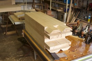
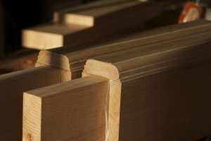
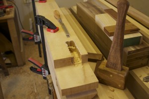
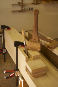
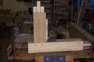
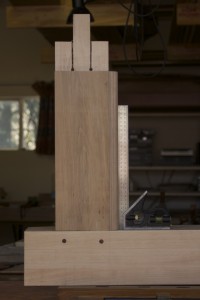
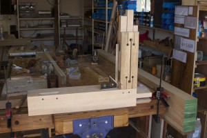
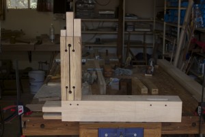
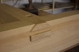
This weekend I finally managed to do the last massaging work needed to fit the short aprons and stretchers to their respective legs. You can see how well it all came together. Thank you David Charlesworth for all the tips in those DVDs that made it possible for a novice to get it done like this. As you can see I added quite a few layers of leather to one face of my heavy dead blow mallet during the previous week in order not to damage the work while tapping these gargantuan tenons home. Once assembled I positioned the legs on the two parts of the twin-top for marking out the through tenons and sliding dovetails.

IMG_1671IMG_1672IMG_1673IMG_1674IMG_1675IMG_1676IMG_1677

I consulted the installation instructions of the Lie-Nielsen twin screw vise to make sure that the position of the legs does not interfere the positioning of the vise. Of coarse I did not keep track of the fact that the table was now upside down and that I needed to consider this when placing the legs and twin screw vise. After I did all the careful marking out and stood back, it dawned upon me that my twin screw face vise would end up on the right hand side of the bench once it is flip over onto it’s legs. Bugger!! So I had to start all over, but still prefer this to not realising and stuffing up the bench completely.

IMG_1678IMG_1679IMG_1680IMG_1681IMG_1682IMG_1683

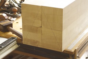
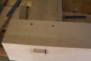
Once the various areas were marked out for the second time, I carefully transferred it to the opposite side and clearly indicated the waste to be removed.

IMG_1684IMG_1685IMG_1686IMG_1687

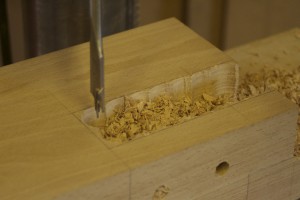
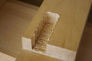
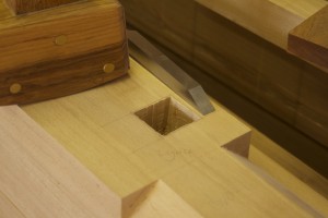
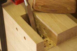
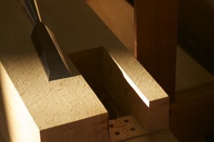
In order to have a slightly more stable top beam to work on I clamped the two part of the top (first picture) together with two pipe clamps. Then I used my Lie-Nielsen tenon saw to cut the sides of the sliding dovetail dado (not sure if this is the correct terminology, but I am sure the pictures will make it clear). The pictures show the sequence of cuts I made in the waste area.

IMG_1690IMG_1691IMG_1692IMG_1693IMG_1694IMG_1695IMG_1696IMG_1697IMG_1698

The chisel did the rest as you can see.

IMG_1702IMG_1703IMG_1704IMG_1705IMG_1706IMG_1707

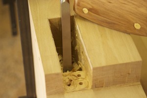
I thought I could use my Lie-Nielsen router plane to clean out the bottom of the sliding dovetail dados but it did not have the required reach.

IMG_1708

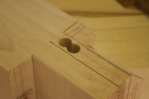
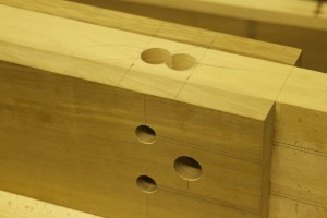
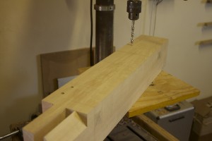
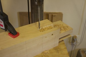
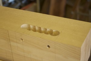
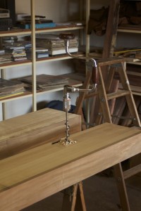
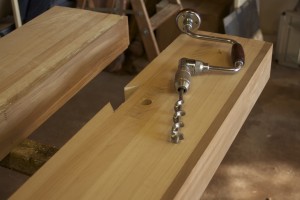
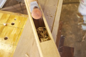
Drilling out the waste from the mortises had to be done by hand as a 1″ drill in a handheld drill would surely destroy the motor in no time. This was thus the first job ever for my new purchased no 923 10″ Stanley brace. It is such hard going that I had to engage the ratchet mechanism to allow me to pull only, rather than trying to go through the full 360º, which is simply beyond my strength.

IMG_1709IMG_1710IMG_1711IMG_1712IMG_1719IMG_1724IMG_1726IMG_1731


21/7/2014

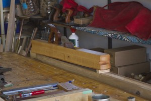
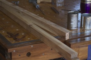
This weekend I started doing further work on the long stretchers, which included final hand planing of the swarthout cleats you’ve met before. In the pictures below you can see how my shop made winding sticks came in handy.

IMG_1749IMG_1750IMG_1751IMG_1753


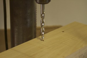
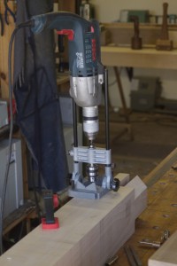
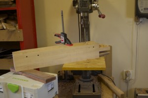
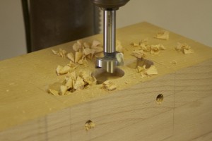
Between working on the stretchers I got so tired of drilling out waste with the brace and bit that I decided to giving the electric drill a go using a spade bit. I first set the drill to it’s slowest (and therefore strongest) speed and realised that it actually made short work of the waste removal. The drill did not even heat up at all, but never the less I did the drilling in many short bursts between other work. Of coarse the downside was that I realised how much religious baggage I still carry, as a peculiar guilt fell over me when the electric drill completed the job I started with the brace and bit.  Luckily it did not manage to get much of a hold on me before moving on to other hand tool work.


IMG_1754


My shop made panel gauge again came in handy to mark out the area on the inside of the long stretchers where I had to remove some Witpeer to accommodate the cleat. I removed the bulk of it with my Festool router and tidied up the mess left with a Stanley no 78 rabbet plane and my shop made shoulder plane. These tools leave a much better finish and enables you to dial in slowly to the absolute exact size of the rabbit needed.


IMG_1755IMG_1756IMG_1757IMG_1758IMG_1759IMG_1760IMG_1761IMG_1762IMG_1763IMG_1764IMG_1765IMG_1765


The next rabbit is meant to accept the endgrain of Kaapse Swarthout boards sitting diagonally on top of the cleat to form the shelve. I used the same sequence of tools used.


IMG_1766IMG_1767

IMG_1768


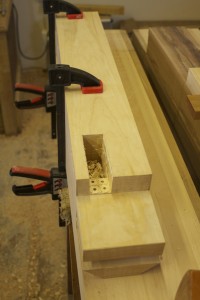
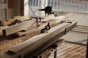
While all this was going on I set up the second part of the twin-top in order to saw and chisel out the sliding dovetail dados. You will notice that I used the cleats temporarily as braces for the Darwinian saw horse as they were a bit wobbly when I did the same to the other part of the twin top. It made a massive difference.

IMG_1769IMG_1770IMG_1771IMG_1777IMG_1778IMG_1779

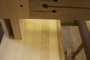
Once again the Festool Domino enabled me to line the additional strip of Witpeer up perfectly with during the lamination process. As per usual, I used the Proletarian sanding contrivances to get rid of machine marks on the glue surfaces.

IMG_1780IMG_1781IMG_1782IMG_1783IMG_1784


3/8/2014

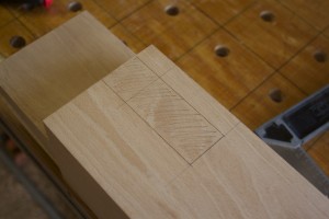
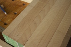
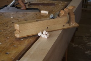
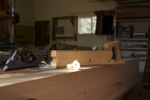
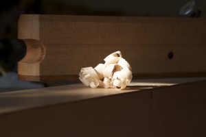
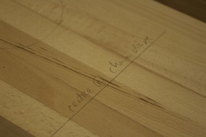
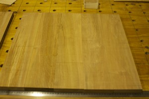
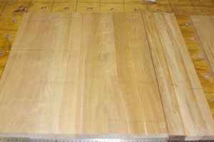
I started cutting the tongue and groove joints on these Kaapse Swarthout boards destined to become the shelve below the twin-top using my Lie-Nielsen tongue and groove plane. The first task however was to arrange the boards so that the edges would fit best in terms of colour and grain pattern. Once I felt please with the arrangement I marked the order using a carpenters triangle.

IMG_1785IMG_1786IMG_1787IMG_1788IMG_1789IMG_1791

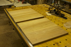
Once I started cutting the joinery, I realised that the boards were obviously thicker than ¾” (the thickness where this no. 48 plane centers on) which meant that another “tongue were left on the male edge of the joint. After taking one shaving I first drew a picture on a piece of paper (pictured) to work out how to fix this problem and realised that I simply had the remove the extra tongue with my #78 rabbet plane and all should be sweet.

IMG_1794

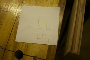
As you can see here.

IMG_1796IMG_1797IMG_1798

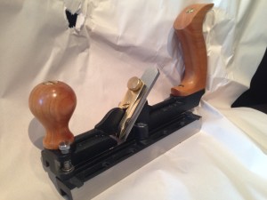
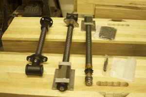
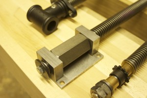
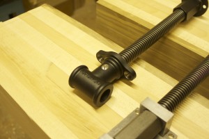
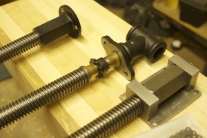
While all this were going on I liberated the Lie-Nielsen vise hardware from the safety of it’s packaging. Here you can see what it looks like.

IMG_1851IMG_1852IMG_1853IMG_1854IMG_1855

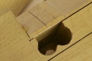
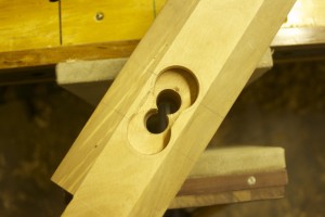
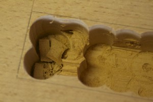
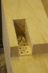
On Saturday I started my next onslaught on the female parts of the leg-to-top joinery.

IMG_1916IMG_1917IMG_1923IMG_1924IMG_1925IMG_1926IMG_1930IMG_1931

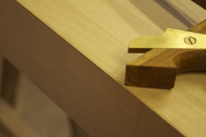
Luckily I had another look in Chris Schwarz’s book on building benches and saw that he actually make reference to the fact that one needs to remove the blade adjuster from our router plane to reach this depth. It meant that I could use this very useful tool to clean out the majority of the through dovetail dado (for lack of a better term), before using that flat surface as a reference to guide my chisel while removing the rest by horizontal pairing.

IMG_1927IMG_1929IMG_1946IMG_1947

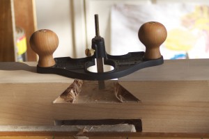
Here are two closeups of the router plane with the depth stop and blade adjuster removed.

IMG_1948IMG_1949

I then took to the long stretchers with my shop made scrub plane to remove the excess timber from the strips I laminated on last week.

IMG_1918IMG_1919IMG_1920IMG_1921IMG_1922


10/8/2014

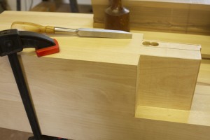
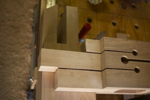
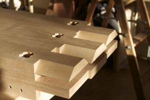
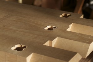
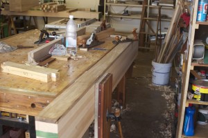
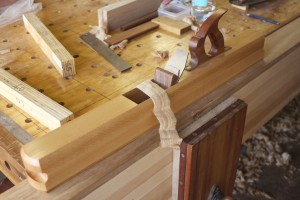
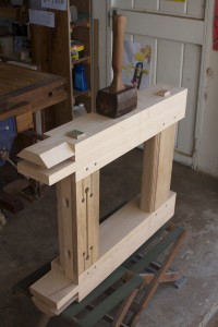
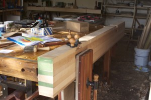
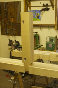
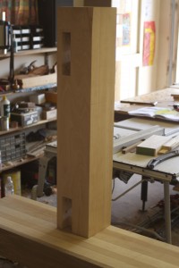
I am very happy to report that I managed to fit two legs to the one part of the twin-top this weekend. The first was quite a mission, but the second not so much. One really needs a healthy dose of patience for this work and it does not help much that I am starting to feel pressured to get the bench assembled before the changes in ambient humidity (probably some time in November).

IMG_1981IMG_1982IMG_1983IMG_1984IMG_1985IMG_1986IMG_1987IMG_1988IMG_1989IMG_1990IMG_1991

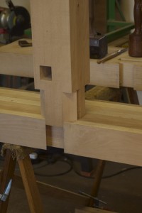
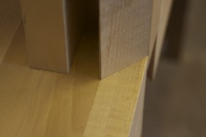
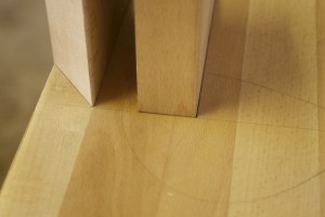
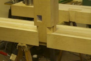
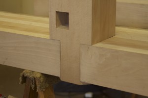
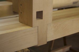
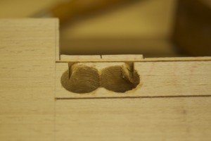
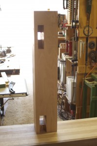
The second leg. You might notice the gaps on either side of the through tenon’s mortise that was created to accept wedges.

IMG_1992IMG_1993IMG_1994IMG_1995IMG_1996

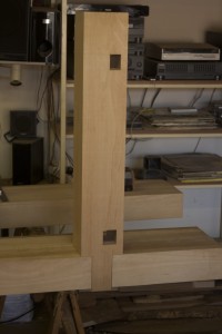
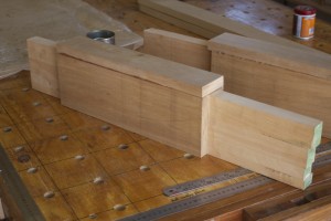
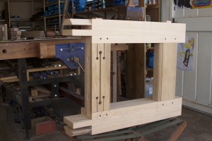
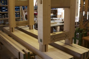
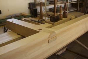
I inserted the apron and took these photos to give you an idea of the base structure of the bench.

IMG_1997IMG_1998IMG_1999

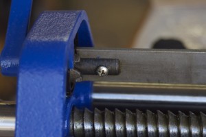
A week ago I started to take the Irwin quick release vise (destined to become the end vise) apart in order to “paint it black”, as I am a Stones man.
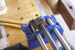
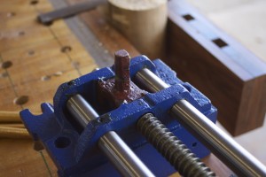
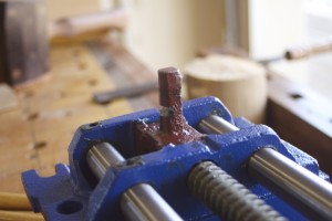
IMG_1939IMG_1940IMG_1941IMG_1942IMG_1943IMG_1944IMG_1945

Didi’s Projects

3/2013

My son Didi (short for Didier) is slowly starting to develop an interest in what is going on in the shop. I thought I should start documenting his progress. Here you can see him building a wild bird feeder.

IMG_5571IMG_5572IMG_5575IMG_5577IMG_5579IMG_5580IMG_5582IMG_5583IMG_5585IMG_5593IMG_5595

31/3/2014

He did the bulk of the work to glue-up and turn his first tool in the form of this beautiful Witpeer mallet.

IMG_0069IMG_0070IMG_0071IMG_0072


IMG_0418IMG_0419IMG_0420IMG_0421IMG_0422IMG_0423IMG_0425

IMG_0427IMG_0428IMG_0429


Project inventory 2012

The major project of 2012 was the assembly table I built, which was also intended to act as a makeshift workbench until I manage to gather a bit more information and skills to build a dedicated one.

http://www.jenesaisquoiwoodworking.com/alternative-workbenchassembly-table-chapter-one/

http://www.jenesaisquoiwoodworking.com/alternative-workbenchassembly-table-chapter-two/

http://www.jenesaisquoiwoodworking.com/alternative-workbenchassembly-table-chapter-three/

http://www.jenesaisquoiwoodworking.com/alternative-workbenchassembly-table-chapter-four/

http://www.jenesaisquoiwoodworking.com/alternative-workbenchassembly-table-chapter-five/

100_0293100_0285100_0271100_0258

I invented and made these benchdogs which works like a charm. I include a photo of how I used it this past weekend while working diagonally across a heavy beam of Witpeer with my shop made scrub plane. They are known in my shop as Bench Bitches.

http://www.jenesaisquoiwoodworking.com/bench-bitches/

100_0295100_0277IMG_0160

One Effulgent Arm.

http://www.jenesaisquoiwoodworking.com/extremely-efficient-effulgent-arm-eeea/

100_0573100_0523

Saw Hook

100_1129100_1130100_1131100_1133

Chopping board for the beach house

100_0582100_0583IMG_3235

Sushi plates

100_0584

Knife rack for the beach house

100_0882100_0883

Sun oven for the beach house

IMG_4031IMG_4032IMG_4033


Dowel plate

100_0558


Spice rack for the beach house

100_0933100_0940


Brace Bit Birdcage Awl (also known as BBBA)

7/4/2014

Once again on Saturday morning I curtailed my current bench building activities briefly in order to produce a so called Birdcage Awl. I found an old Marples & Sons brace bit that had most of it’s business end missing in action. The square tang of the bit that fits in the brace made me think that it could masquerade successfully as a Birdcage Awl without too much fuss. The steel is obviously top notch as the bit is probably more than a hundred years old.

IMG_0112

The bit comes from my father’s collection. I tried to take a photo showing the Marples & sons stamp, but I probably need a macro lens for that. The small block of Witpeer was left over from another project and had the ideal dimensions for me to turn the handle from.

IMG_0113IMG_0115IMG_0114

… as so.

IMG_0116IMG_0117IMG_0118


I first did the bulk of the shaping with the bench grinder and then run through 80, 100, 120, 180, 240, 360, 400, 600 and finally 1200 grit wet-and-dry sandpaper on glass.

IMG_0119IMG_0120IMG_0121IMG_0122IMG_0123


The handle received a copper ferrule …

IMG_0124IMG_0125IMG_0126

… before I drilled a tapering hole with several different diameter drill bits to accept the shank of the brace bit. It was only tapped home (much like the way one would seat a rasp), as one would need to be able to remove the bit for future sharpening.

IMG_0127IMG_0128IMG_0129IMG_0131IMG_0130IMG_0132

Finally, it received the usual treatment with successive layers of Tung oil/Ballistol and Wooddock. This is an excellent awl for making holes to accept wood screws in softer wood where pilot holes are not needed. The square edges cuts the wood fibers to open up the hole as apposed to a round point awl that only separates the fibers.

IMG_0177IMG_0178IMG_0182IMG_0180


IMG_0306IMG_0307IMG_0309IMG_0308

Sustainable cuisine

11/2012

A few months ago we bought a holiday house in Groot Brak Rivier and I decided to build a sun oven to use while sitting in the sun with a beer. In the pictures below you can see how I bent and riveted aluminum to create the business end of the oven. The idea is to reflect all the sun rays on to a black casserole type dish to create a truly eco-friendly slow cooker.

100_0703


100_0802100_0803100_0801100_0804100_0805


100_0811100_0812100_0813


100_0818100_0819100_0820100_0822

Before building the base I tested the contraption my cooking a curry amongst the herbs and chillies in our herb garden. Even this red le Creuset casserole absorbed enough energy to cook a beautiful Madras.

100_0828100_0831

I then built a base for it from bits of scrap plywood.

100_0855100_0856100_0857100_0858100_0860100_0861100_0862100_0865100_0864100_0866100_0867100_0868100_0870100_0871100_0872100_0873100_0874100_0875100_0884100_0885100_0886100_0888100_0889100_0890100_0892100_0892100_0930-2

In the pictures below you can see it in action at our beach house. The oven is closed with a sheet of glass or transparent perspex to limit air movement.

IMG_4031IMG_4032IMG_4033IMG_4042


Over this past December (2013) holiday, I cooked a leg of lam from scratch in it.

Chisel storage

17/3/2014

On Saturday I briefly interrupted my bench-building-activities in order to ensure that my precious new Lie-Nielsen bevel-edge chisels receive a warm welcome and safe haven right from the start of our (hopefully) long and prosperous relationship. I ordered these chisels back in November 2013, but the tool works at Lie-Nielsen were out of stock and in the process of crafting new ones. As far as what I can gather they had a few hiccups in this process, which meant that the chisels only arrived on 10/3/2014. The guys and gals at Lie-Nielsen leave no stone unturned when it comes to their commitment to ensure the absolute highest quality, which was again quite obvious when I unpacked these heirlooms.

IMG_9974IMG_9975IMG_9976IMG_9982IMG_9983IMG_9984IMG_9985IMG_9990

An example of the attention to detail is how the backs of these chisels have been perfectly flattened by hand honing. This means that you have the absolute minimum preparation honing to do before you go mental with it on a piece of timber.

IMG_9987IMG_9988

Just look at these stunning Hornbeam handles. I plan to turn my own longer handles for when I am using the chisels for paring.

IMG_9989

Here you can see how I very quickly built a rudimentary chisel dwelling from a piece of scrap Swarthout. Swarthout (Acacia melanoxylon and known as Australian Blackwood, Sally Wattle or Tasmanian Blackwood) originates from Australia (surprisingly) as a species, but this particular piece is South African by birth as it spent many years enjoying the tranquility of the rain forests of the Garden Route.

IMG_9993IMG_9994IMG_9995IMG_9996IMG_9997IMG_9998

I decided that the quickest way to keep the chisels sitting stable and upright (as the three smallest chisels are top heavy and therefore tends to attempt acrobatics in it’s dwelling) was to whack dowels through the living room.

IMG_9999IMG_0001IMG_0002

Together with the dowels, a small notch on the inside of the side walls where each chisel’s socket rests, does a great job of keeping each chisel proud and upright.

IMG_0003IMG_0005IMG_0004


At this stage I left the dwelling as is, but might add a base once my bench is finished, because it might be useful to grab the who set and stick it on the bench next to you while doing dovetails or mortises. For now it will be supported by two storage containers on either side of it in my tool rack.


IMG_0109IMG_0110

Braaivleis borde

7/2/2014 – I laminated this board using Ystehout (wide strips), Kershout (dark strips), and Witpeer (edges) back in the latter stages of 2012. It then sat in the shop until the end of 2013 before I had the gusto to turn it into something useful. We were getting ready for our Desember holidays, so I decided that it should become braaivleis borde.

IMG_8660IMG_8661

I first cleaned up the long edges with my shop made jointer to ensure that the router would glide smoothly. The pictures also show how my shop made Legvise and sliding deadman function in tandem.

IMG_8662IMG_8663IMG_8664


I decided to keep the board intact for for the routing of the grooves meant to catch liquids.

IMG_8665IMG_8666

Then I chopped it up into the individual boards and routed the rest of the grooves.

IMG_8667IMG_8668

Here you can see how my assembly table assists with holding the plates while I route the grooves at either end of the board meant to act as a grip for picking it up.

IMG_8669IMG_8671IMG_8670

The plates were finished off by means of a few coats of liquid paraffin.

IMG_8680IMG_8681

Stanley no. 78 Rehabilitation

4/2/2014 – I bought this old Stanley #78 rabbet plane at an antiques auctions during the December holidays in Groot Brak Rivier. As you can see it was in a pretty bad state. The parallel guide and the lever cap were missing, but the depth stop and the nicker survived.

IMG_9038IMG_9039

It had one bade that was held in place by a washer as you can see.

IMG_9040

Here you can see the depth stop and nicker.

IMG_9041IMG_9042IMG_9043


Since I struggled for a day with paint remover and wire brushes on a handheld drill to remove the japanning from the 2 cast iron fore planes I restored recently, a friend told me of a engineering shop that does bead blasting. The idea seems to be that these beads only removes paint and rust but no metal. So I rang Kenney at the Prop Shop who quickly explained what they do. Within 3 days I received a #78 looking like this ….

IMG_9613IMG_9614


I could not believe my eyes and thought they decided to plate it with something or other, so I rang Kenney. He assured me that it was only bead blasted and on closer inspection I realised that he was correct. As soon as I arrived home I proceeded to stick masking tape on all the areas that needs to stay paint free.

IMG_9615IMG_9616IMG_9617


Then I applied a coat of rust converter.

IMG_9618IMG_9619IMG_9620


10/2/2014 – Next came a coat of a rust resistant undercoat …

IMG_9623IMG_9624


… and three layers of high gloss truck enamel paint.

IMG_9637IMG_9638

IMG_9865IMG_9866


24/2/2014 – Seeing that the plane lost it’s lever cap, I fashioned one out of brass to give it that Lie-Nielsen look.

IMG_9898IMG_9899IMG_9900IMG_9901


17/3/2014 – Speaking of the devil, at about this time the Lie-Nielsen replacement blade arrived with a set of bevel-egde chisels.

IMG_9975IMG_9977

As you can see the news blade is almost an exact replica of the original except that it is quite a bit thicker. This has the added benefit that it closes up the throat.

IMG_9978IMG_9980IMG_9979


New blade and lever cap in position.

IMG_9981


31/3/2014

I started cleaning up the thread were the MIA fence guide should screw in.

IMG_0055IMG_0056IMG_0057

I then fashioned a new guide out of brass.

IMG_0058IMG_0059IMG_0060IMG_0062

The depth guide received the same treatment as the plane …

IMG_0061

22/4/2014

… and fitted to the plane.

IMG_0225IMG_0226


19/5/2014

During the past weekend I finally fashioned this Dolce&Gabbana-esque fence as I needed it to do some hand-cut mouldings. I might work on it’s appearance a bit more in future and possibly add a knob to the side that screws onto the end of the guide. Watch this space.

IMG_0919IMG_0920IMG_0928IMG_0929IMG_0930


A few examples of the mouldings.

IMG_0932IMG_0933IMG_0927

My 18th Century Workbench in progress 3

A Treatise on lamination and planing elbows

2/2/2014

I started building my dream workbench this weekend. The beech has been sitting in the garage since December 2013, patiently waiting and settling into the rainy season. The average humidity in the shop has risen from 20-30% to anywhere between 50-75%. Before we left for holiday in South Africa I stacked the boards in the wood store with a 100 mm thick x 300 mm x 2500 mm slab of Ysterhout (which weighs a freaking lot) on top of it and quite a few other hefty items on top of that. When I removed these constraints on Saturday, it seemed as if it did the necessary to prevent unwanted movement.

Here you can see my beautiful wife with the beech that is destined to become the top of the workbench. At present the pile is made up predominantly of boards of 37 mm-ish x 110-150 x 2400 mm. There are also two 45 mm-ish x 2700 mm boards.

IMG_9580


In the picture below you can see the 4 boards destined to become the legs. They were in the order of 45 mm-ish x 130-150 mm x 2700 mm.

IMG_9581


I chopped each up into three 900mm long sections.

IMG_9583IMG_9582


The plan being, to laminate each triplet into one leg.

IMG_9585IMG_9586IMG_9587


I devised the following plan to keep the boards waiting to be laminated straight. You can see how I used my Bessey clamps in reverse to put pressure on the stack.

IMG_9588IMG_9589IMG_9590


I ran each board thought the planer and removed the machine marks with the two smoothing planes pictured to created an ideal glue surface. The pictures show how I scribble on the faces to make sure everything gets planed.

IMG_9599IMG_9598IMG_9600


The first leg were glued on Saturday and were left in the clamps for 24 hours before the second leg got it’s turn on Sunday.

IMG_9591IMG_9592IMG_9593IMG_9597


10/2/2014 – If you are smart you can get your wife and son to carry the lumber around for you. Here you can see how my assistants carried the boards destined to become the top and the stretchers up to the workshop.

IMG_9625IMG_9626IMG_9627IMG_9630

My apprentice (also known as the wife) agreed to help with the task of ripping the boards to width on the bandsaw, a task that is impossible to accomplish all by myself.

IMG_9629IMG_9631IMG_9633IMG_9634IMG_9636

I then stacked and clamped them to prevent major movement while they await the arduous and slow lamination process.

IMG_9639IMG_9640

The next step was to feed them to the planer who happily took care of the rough faces which would become the glue surfaces during the lamination process.

IMG_9867IMG_9868IMG_9869IMG_9870IMG_9873IMG_9872


24/2/2014

Here I played around with the different boards to identify the outside boards and best order for the lamination of the two parts of the top.

IMG_9875

The first of 15 separate glue-ups. As you can see, I used my Festool Domino in order to get the edges of the boards more or less flush during this lamination process. I only added one board each time and would then leave it in the clamps for a minimum of 24 hours before adding the next. The preparation and glue-up took around two hours for each step. As you can see I prepared the machine planed faces further by removing the machine marks with my shop made proletarian sanding contrivances (also known as sanding planes). One cleanup with 120 grid followed by 150 grid to get a really good glue surface. My shop made glue roller is also in action, showing off how useful it can be during major glue-ups like this.

IMG_9876IMG_9877IMG_9879IMG_9880IMG_9881IMG_9882IMG_9883IMG_9884IMG_9908IMG_9909IMG_9910IMG_9885

Here you can see how I removed the excess hardened glue with my shop made flush plane and then proceeded to flatten and square up two reference surfaces before once again feeding the legs to the planer. I first removed the bulk of material with my shop made idiosyncratic scrub plane and then followed up with the two cast iron fore planes I resurrected earlier this year. One (the Stanley Bedrock) of the fore mentioned is set up with an aggressive cambered blade (centre in the picture showing the various shapes of cutting edges) and the other (the Record) more similar to a smoothing plane with an ear-clipped flat blade (left in the picture showing the various shapes of cutting edges) and a tight throat. The last picture shows my makeshift winding sticks.

IMG_9888IMG_9889IMG_9915IMG_9916IMG_9890IMG_9892IMG_9893IMG_9896

Leg after the planer had it’s say.

IMG_9897

The first halve of the twin-top progressing slowly with the passing of many days.

IMG_9912


10/3/2014

By this time I worked out that the two parts of my twin-top would end up about 40mm (in total thus 20mm each) narrower in width than intended. This of course due to the unpredictability of width after planing the boards flat and ultimately not buying quite enough wood. Therefore I decided to add 20mm to each by means of yet another lamination of Witpeer to the inside of each. My plan was in any case to make up for the slight shortage of beech by adding Witpeer. This would make the bench quite unique and add some African je ne sais quoi (of course).

Here you can see how I liberated the strips of Witpeer I needed for the insides of the tops from a feral plank straight out of the Knysna forest. The last three pics show the liberation of the strips of Witpeer meant for the lamination of the breadboard end that will stabilize the twin-top at one end.

IMG_9919IMG_9920IMG_9921IMG_9922IMG_9923IMG_9925IMG_9924

The two parts of the twin-top before the Witpeer strip were laminated on.

IMG_9927IMG_9929IMG_9928

Adding the Witpeer strips.

IMG_9932IMG_9933IMG_9935IMG_9936

Here I started flattening a face of the top in order to create a perfect reference surface to flatten the opposite side parallel to it in the planer. I cleaned off the hardened excess glue with my shop made flush plane and then started the arduous process of removing the bulk of the waste with my shop made scrub plane. As you can see it was quite a mission, but the scrub plane performed admirably and although it was tiring, I actually enjoyed it’s aggressive attitude.

In the pictures below you will see how I worked diagonally across the top, first in one direction and then the other. I took a photo after each pass to show the progression. Towards the end of this process I made sure I took care of most of the very slight wind, even before moving on to the fore planes.

IMG_9951IMG_9952IMG_9953IMG_9954IMG_9955IMG_9956IMG_9957IMG_9958IMG_9959IMG_9960IMG_9961IMG_9962IMG_9964IMG_9965


Then I took to it with the two cast iron fore planes. First the aggressive bastard, followed by the gentle giant.

IMG_9966IMG_9967IMG_9968IMG_9969IMG_9970IMG_9971

As you can see, it worked very well as it came out of the planer looking pretty tidy.

IMG_9972IMG_9973

At this stage I managed to slowly work my way through the same process (as above) with all the legs. They were now all square and flat on four sides but in slightly different dimensions. Therefore I needed to pass them through the planer until they were exactly the same dimensions. You will see how I first marked the reference surfaces on the ends because the marks indicating them on the faces would disappear soon. In the end I ended up with legs of 132mm x 134mm.

IMG_9930IMG_9931IMG_9940IMG_9941IMG_9942IMG_9943IMG_9944IMG_9945

Didi and Aoife helped to clean up the shavings and used it as mulch around the trees outside the shop.

IMG_9947IMG_9948

As if I haven’t done enough lamination by this time, I had to start laminating the relatively thin strips that fell off while ripping the boards for the top to make up the four stretchers and two aprons.

IMG_9937

This is supposed to become the two aprons, but will receive some Witpeer reinforcement as well.

IMG_9950


17/3/2014

This is the first of two laminations destined to become the stretchers.

IMG_0012IMG_0011IMG_0018IMG_0019IMG_0020


Next I attacked the second of the two beams being moulded into a twin-top with the blood-thrist trio of hand planes. I really like the scalloped appearance of the face being left by the scrub plane.

IMG_0006IMG_0007

I managed to inflict this cut on my shin by bumping into the first top’s edge while planing the second. These tops are so heavy that it really is a major exercise to pass it through the planer a few times. Luckily, my beautiful assistant (who likes to be referred to as my wife) helped me as it would be utterly impossible otherwise.

IMG_0010


Here are (literally) the products of blood sweat and tears, quietly resting until I manage to gather strength and time for the next assault on their configuration.

IMG_0008IMG_0009

Another, challenge I face over the past several years is dealing with the fact that water tends to invade on my privacy in the shop. Despite paying so-called roofers NA$5000 dollars last year to fix the problem before the next rainy season, I am still swimming on a fairly regular basis.

IMG_0013IMG_0014IMG_0015IMG_0016IMG_0017

31/3/2014

The two boards laminated from all the offcuts destined to become the four stretchers before receiving some attention from the planer.

IMG_0022IMG_0023

In the pictures below you can see how I prepared and laminated Witpeer to from a very solid hunk of African hardwood destined to become the so called breadboard end of the bench’s twin-top.

IMG_0024IMG_0025IMG_0026IMG_0027IMG_0028IMG_0030IMG_0031IMG_0042

Next I laminated the two short aprons. The table will only have these two aprons as the top is thick enough to get away without the long aprons. The two short aprons is needed to keep the table together as it will have a top consisting of two separate beams with a breadboard end at at one end only. In the second picture you can appreciate the grain orientation of the beech that will form the centre of the apron. I spent quite a bit of time to find the right piece of wood in order to make up a board that is essentially quarter sawn. The reason for this is that as you probably (seeing that you are reading a woodworking article) know, quarter sawn boards do not move much in it’s width (as compared to plain or rift sawn) as other boards. I wanted this particular characteristic for the two short aprons as my two-piece top will shadow any movement in the width of the aprons, possibly leading to unwanted changes in it’s alignment. You will notice that I continue to use Dominos to ensure that at least one edge of the boards being laminated stay flush with all the others.

IMG_0032IMG_0033IMG_0034IMG_0035IMG_0036IMG_0037IMG_0043IMG_0044IMG_0045

In the pictures below you can see how I attacked the legs with the awesome foursome (first picture). I found that after planing them down to the same dimensions with the electron dependent planer and resting a while they went ever so slightly out of square. I managed to sort out two of them in this session.

IMG_0039IMG_0040IMG_0041

At this stage I had to go and find a bit more Witpeer to strengthen the beech laminations destined to become the stretchers. In the first picture you can see the feral planks liberated from the Knysna forest more than 10 years ago. I then used the bandsaw to rip them into a more respectable shape. After that I plane them a bit, but as you can see not completely flat. I decided to let the boards settle for a few days before doing the final planing. You can see how I clamped the boards to my assembly table to keep them honest while resting.

IMG_0046IMG_0047IMG_0048IMG_0049IMG_0050IMG_0051IMG_0052IMG_0053IMG_0054

The boards after the next planing and the usual preparation for lamination of the side (long) stretchers.

IMG_0064IMG_0067IMG_0068IMG_0073IMG_0074IMG_0075IMG_0076IMG_0077IMG_0078IMG_0079IMG_0080IMG_0081IMG_0085IMG_0086IMG_0099IMG_0100IMG_0101

I then went looking for Swarthout (Tasmanian Blackwood) to mill down and use where no one can see it such as cleats for the shelve between the stretchers. Even though this particular piece of Swarthout originates from Africa, I would feel very embarrassed to use Ozzy wood in any other location. This is also (for obvious reasons) not the best Swarthout boards one can find.

IMG_0087IMG_0089IMG_0094IMG_0107IMG_0108IMG_0111

During a short break I drew a picture on the Swarthout to work out what size of the strips should be that I need for the cleats. My father used to draw on the wood like this, but he did not draw on the wood he was about to rip as I did. I realised this a bit too late, but hopefully will remember for future reference.

IMG_0091IMG_0092IMG_0093

This is my friend Paulus, he guards our street. Yes, that is a shot gun he is hold in his left hand. This is Africa (or simply TIA if you are a local) as they say. Paulus likes having a chat every time he passes the garage and is a keen follower of the progress made on this workbench. I think he is probably wondering why someone would take so long to build a workbench.

IMG_0088

Here you can see the, by now, overly familiar process of laminating the end (short) stretchers.

IMG_0095IMG_0096IMG_0097IMG_0098IMG_0102IMG_0103IMG_0104IMG_0105


7/4/2014

This weekend I continued my diligent lamination/milling frenzy. I found these exquisite Kaapse Swarthout (Maytenus Penduncularis or Cape Blackwood) boards in my collection and decided to use it for the shelve between the stretchers of my bench. In the final picture you can see the attractive orange colour of the 120 mm strips I ripped for the shelve.

IMG_0134IMG_0136IMG_0151IMG_0154


The pictures below show the last of the major laminations, where I added the inside strips of Witpeer to the side (long) stretchers. The routine must be very familiar by now. I had a quick look and realised that the first laminations was done on the 1st of February 2014, which means that it took exactly 9 weeks to complete the bulk of the lamination phase of this project. You must be exceedingly bored by now! You will therefore be delighted to hear that I am already working on the next riveting installment of this workbench-building series entitled “My Workbench 4 (joinery and armament)”. The so called “light at the end of the tunnel” has appeared at … well … the end of the tunnel.

IMG_0138IMG_0139IMG_0140IMG_0141IMG_0142IMG_0143IMG_0144IMG_0145IMG_0146IMG_0147IMG_0148IMG_0149IMG_0150

After the breadboard end had a week or so to settle after lamination, I took to it with the usual suspects (flush plane, scrub plane, #607 Bedrock fore plane and finally the electron imbibing planer) in order to square it up for the impending joinery phase.

IMG_0155IMG_0156IMG_0157IMG_0159IMG_0160IMG_0161IMG_0161IMG_0162IMG_0163IMG_0164IMG_0165

During the latter part of Sunday afternoon I started to pile all of the gargantuan parts of the bench on top of each other to catch some autumn sun. I also managed (with the philanthropic help of the wife) to bring both parts of the twin-top-to-be down to the same thickness and did the same with the legs after they were found to be ever so slightly out of square after the previous attempt (and a week or two of resting/settling).

IMG_0168IMG_0169IMG_0170

At the end of the weekend, I placed the two parts of the top on my shop made Darwinian saw horses in exactly the position it will assume on the bench. You can see the 100 mm gap between the two parts of the top that is intended to accept F-style clamps to improve one’s ability to clamp all sorts of objects to the bench. The top is also in the exact location (in the shop) it will occupy once finished. I apologise for the poor quality of the pictures due to the late afternoon sun.

IMG_0172IMG_0173IMG_0174IMG_0175IMG_0176


22/4/2014

I remember learning about a “tennis elbow” at medical school, but all this hand planing seems to have given me a “planing elbow”. Has anyone else developed such an ailment? It is bloody sore and getting worse as there are lots of squaring-up to do after all the laminating. In the pictures below you can see how I attacked the two aprons with the usual suspects. After establishing two reference surfaces I used the marking gauge to get both aprons to the same width by hand as they are to wide to fit upright through my planer. In the process I discovered that I can use my shop made wooden scrub plane as a very aggressive fore plane to remove the bulk of the waste. It’s extra length also came in handy to get everything flat and parallel to the reference surface. Once I got close to the line I switched to my #606 Bedrock fore plane.

IMG_0202IMG_0203IMG_0205IMG_0206IMG_0207IMG_0208IMG_0209IMG_0210IMG_0212IMG_0213IMG_0216IMG_0217IMG_0228

24/4/2014

I went as far as doing some web based research on my ailment which I aptly named “planing elbow”. I had delusions of grandeur envisioning the fame that would inevitably befall me if I become the first doctor to describe this new syndrome. I even considered calling it “Marx Elbow”. You know like Alzheimer’s Dementia or Wernicke’s Encephalopathy. While imagining all this like John Lennon, I was rudely brought back to earth when I found that there were heaps of woodworkers who already wrote about my new ailment. Damn! Now I still have an overuse syndrome, but no fame to dull the pain.

Anyway, it seems as if one of the fundamental reasons why I am building the bench might be the reason for my affliction. Most commentators seems to suggest that a too high work surface might exaggerate the problem. My assembly table is around 36″ high which is far too high for heaps of hand planing. It makes a lot of sense, come to think of it, as the higher the surface the more you have to use your arms (as apposed to your legs). Unfortunately, I have quite a bit more planing to do in order to finish the bench, which will become my lower planing surface. Maybe I should consider giving the wife some planing lessons??

28/4/2014

With me needing some help being injured, Didi jumped in to help “die Pappabeertjie” remove excess glue before I started planing the short stretchers.

IMG_0342IMG_0343IMG_0348IMG_0353IMG_0361IMG_0362

I followed the same procedure as with the aprons.

IMG_0363IMG_0364IMG_0365IMG_0366

Then moved on to the long stretchers.

IMG_0368IMG_0369IMG_0370IMG_0371IMG_0372IMG_0373IMG_0374IMG_0375IMG_0417IMG_0415IMG_0416


IMG_0426IMG_0430IMG_0431