All posts by Gerhard Marx

Psychiatrist and Woodworker

Reuleaux Table – The Dessert

6/8/2018

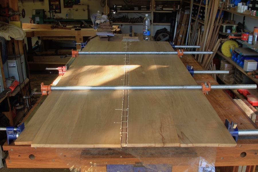
Finally we have chomped our way through the formalities to arrive at the Crème brûlée of the project.

Whoa! I feel good, I knew that I would, now
I feel good, I knew that I would, now
So good, so good, I got you

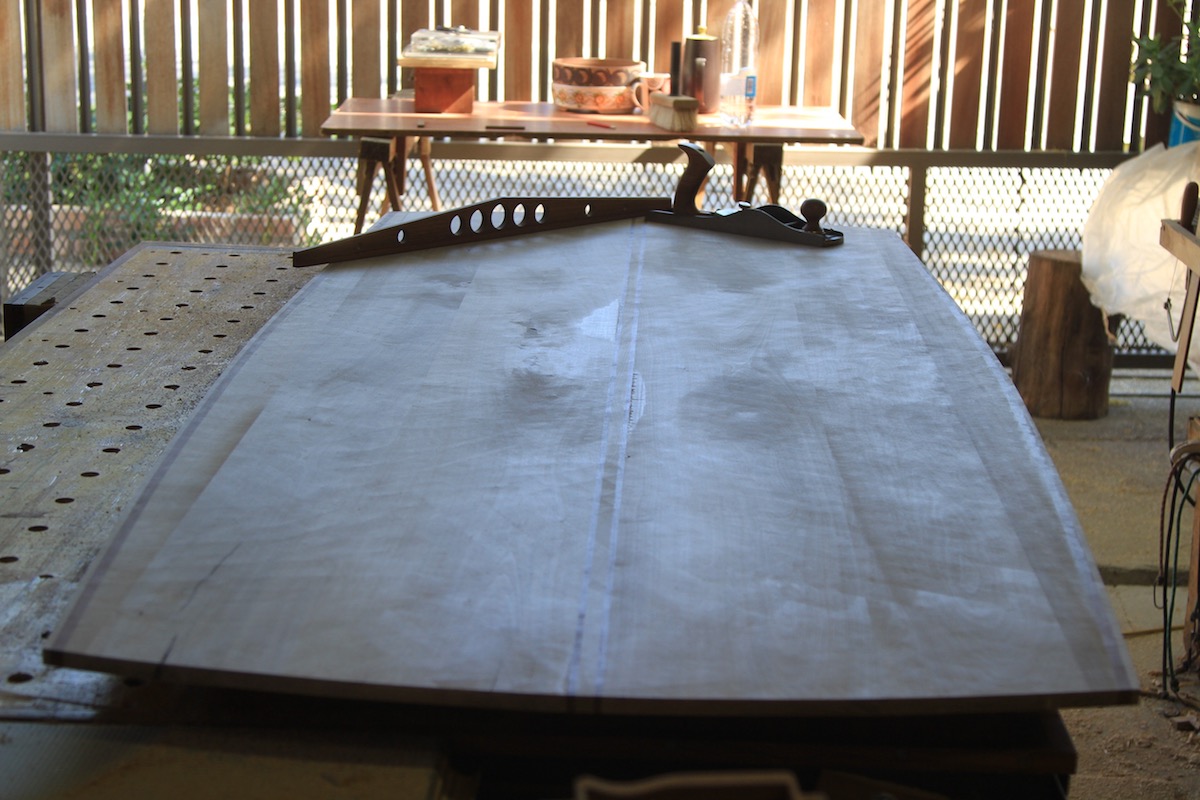
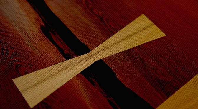
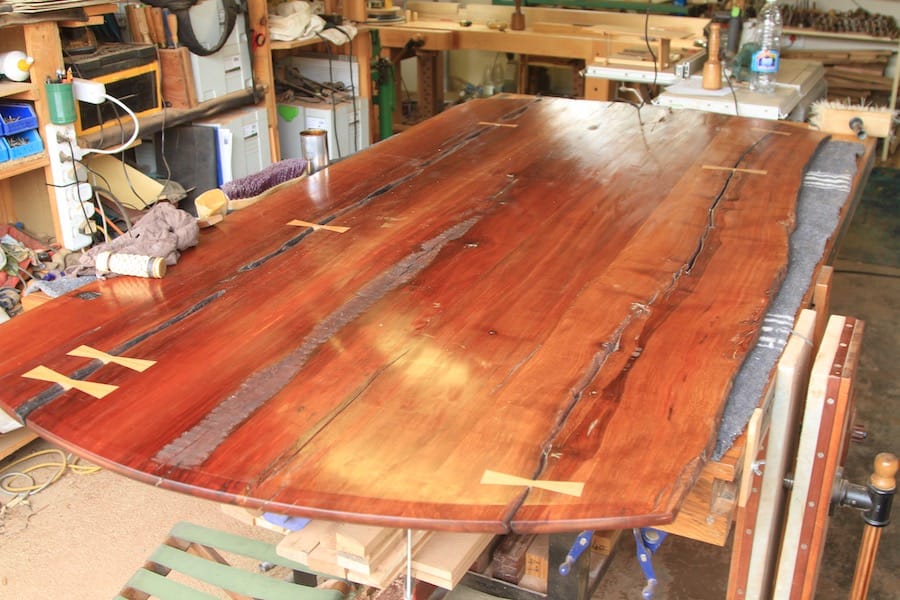
Anyway let’s get back to the woodworking James Brown. The long board shaped top had the odd defect that was filled it with a mixture of beeswax and Carnauba wax. I heaped some of the wax on top of the said defects and then carefully torched it with a flame.

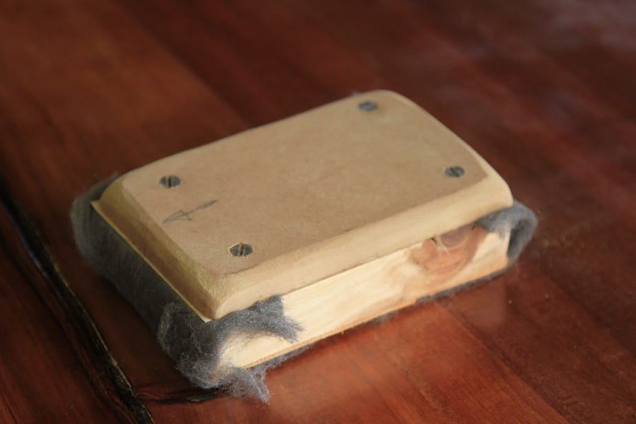
Once the wax was melted into the defect I removed the excess with a small block of wood used in the same manner as a scraper. I find that there is a sweet spot when it is best to remove the excess. If you wait too long the the wax is too hard and tends to rip bits out that should have stayed intact. If you jump in too early the wax in the defect continues to shrink and you end up with a slightly hollow spot.

For some unknown reason I convinced myself to rely on 21st century technology to drill out the angled holes for the leg tenons. Yes I know, I should have known better.

The first step was to drill a small pilot hole at the correct angle.

That was then followed by an attempt to drill out the rest using this absolute waste of a piece of cheap metal. Half way through my first attempt the so called bit got warped like a soft serve ice cream. On the upside it was just another reminder that I should simply stick to my old hand tools made before the Great War. Since then quality has really left the house, so to speak.

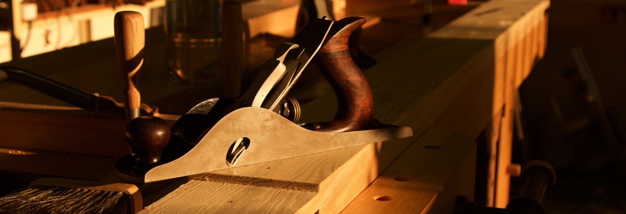
A 14″ brace paired with an appropriately sized Irwin bit made short work of what seemed like an impossible task to humanity’s more recent attempts at tool manufacturing.

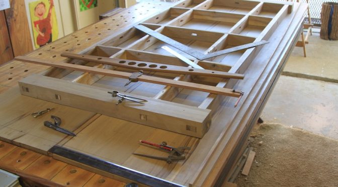
Before proceeding to ream out the mortises for the legs, I had to turn a ‘testing stick’, by lack of a better term. It is a very useful aid to test that you are in fact proceeding at the correct angle while reaming. In order to finish the testing stick, I had to fashion the tenon cutter for this particular job. Both these shop made paraphernalia can be seen in the pictures below.

The testing stick in action. You simply stick the stick (mmmm?) in your partially reamed hole and check it with a bevel set to the desired angle. My shop made reamer can be seen resting next to the stick.

Just to contradict myself thoroughly, I have to mention that I might consider the Veritas metal reamer for future mortises of this size. My shop made version struggled with the load created by the large diameter and extreme hardness of the Witpeer. Veritas has a reamer bit that fits on a hand brace, which should make this exercise easier and possibly improve the tolerance of the mortise.

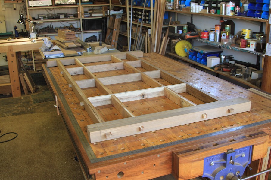
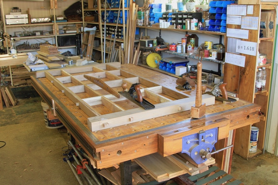
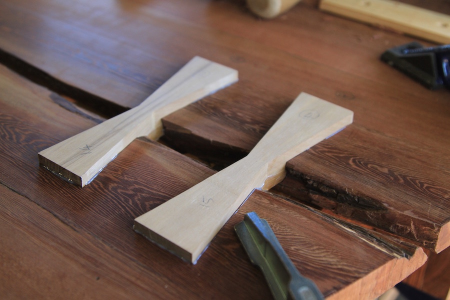
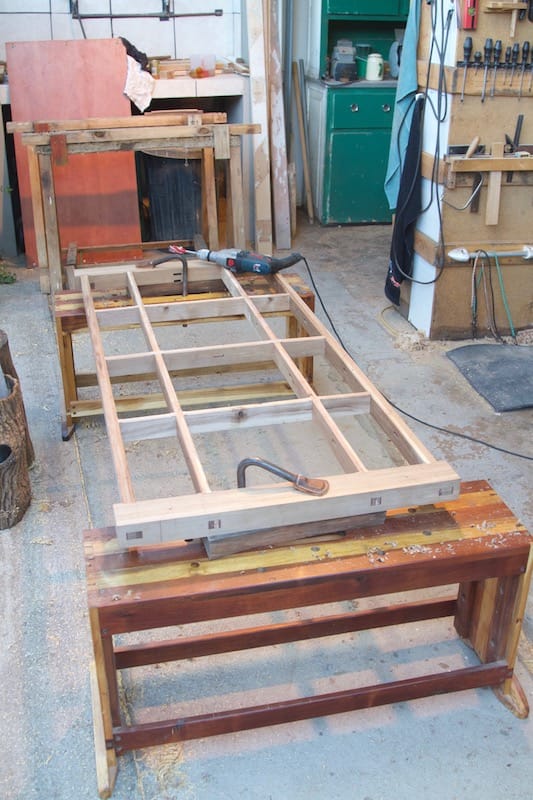
Once the mortises were done, I had to finish shaping the legs. I would say that the biggest surprise of the entire project was how much effort it takes to shape legs like this by hand. It took weeks of hand planing to shape the tapering octagonal design. Having said that, now that it is finished it was all worth while as the end product is absolutely spot on.

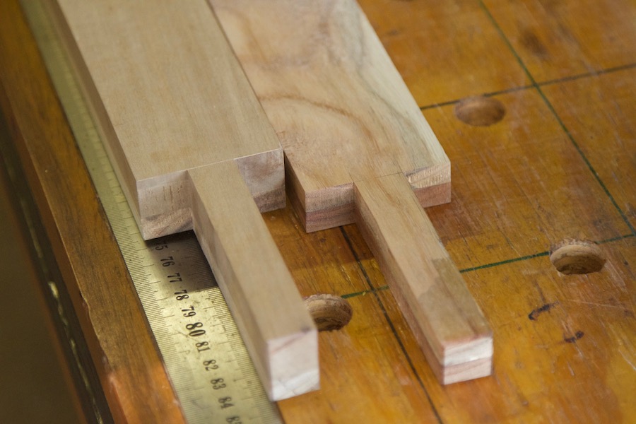
The tenons were turned to a smidgen larger than needed.

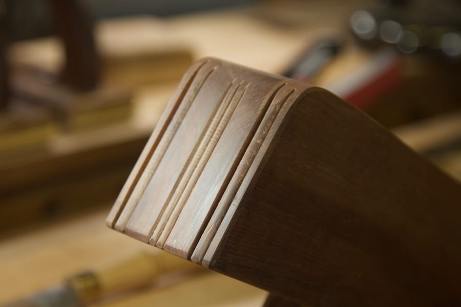
They were then taken to exact dimensions by feeding it to the tenon cutter.

First leg in it’s mortise. You might be able to discern my makeshift plumb bob testing whether my angle calculations were in fact on the money, in terms of where the leg ends up relative to the edge of the table. Turns out that by some stroke of good fortune, my geometry skills are still with me. That is for the moment anyway.

The tenons were taped off before applying oil followed by shellac.

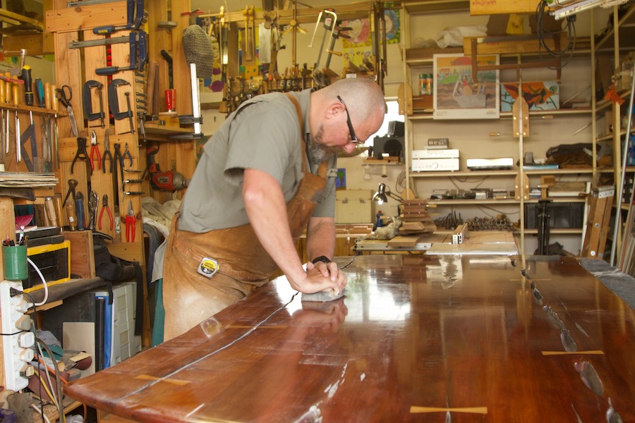
Speaking of shellac, Mr Miyagi returned for a Karate Kid sequel to finish off the top with said substance.

This time round however I did not waste time by trying to find commercial products to add a protective layer over the secretions of the female Kerria lacca bug. No, I made my own furniture wax while applying the principles of the 1516 Bavarian Reinheitsgebot. In other words, only four ingredients all completely natural. No unknown chemical, to cut corners and ultimately cheapen the quality. The ingredients are as follows: Beeswax (from South Africa), Carnauba wax (from Brazil via Germany), Coconut oil (from Indonesia), Olive oil (from Greece). No more, no less.

In the pictures you can see how my double boiler setup on top of a fairly nasty South African made Primus stove were used to melt the components together. This particular stove is a sorry wannabe compared to the legendary brass models built in Sweden prior to the involvement of pelf peckish corporate halfwits who managed to kill another icon of nobility. Despite that, it is still better than anything you can buy new 40 years later. Sad isn’t it?

My concoction prior to setting. It smells superb …

… and functions even better. After application I left it for a few hours and then buffed off the excess. You will have to wait for the final pictures to see what that looks like.

The legs ended up seating exceptionally well in their respective mortises. I do find it particularly stressful to smash them home with my heavy dead blow mallet, but luckily nothing untoward happened. The mortises were all flared out on the exit side to allow for the introduction of two wedges each. These ensure that the joinery has both mechanical and glue strength.

I also made a special ‘screw-set’ formula using natural waxes and Ballistol mineral oil. It works really well on these old school wood screws in hard wood. It helps to make it easier to set the screw and protects against corrosion for many years to come.

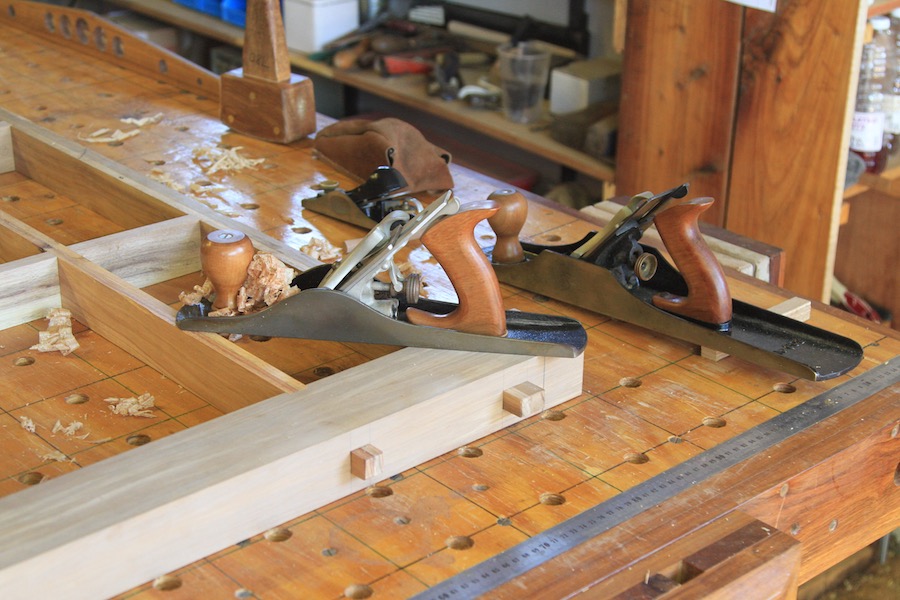
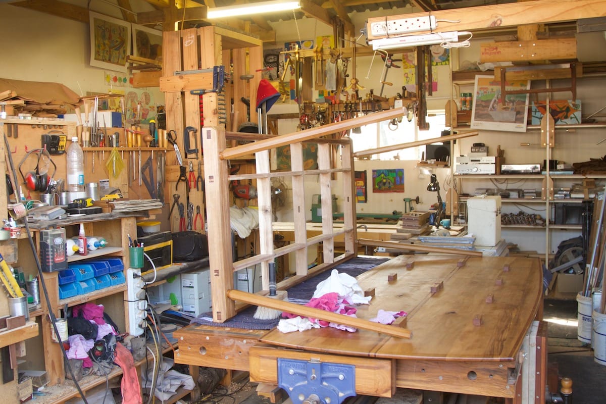
With the table assembled it was time for a photo with these two scalawags.

Marking out the final length of the legs and angle to cut.

We moved it to the kitchen in two piece and reattached the top there.

There you go James Brown.

The table quickly become known as “The Long Board” in the Marx household. I hope you enjoyed this gastronomic woodworking journey. Stay tuned for our next project which will be a Japanese style bed.

Reuleaux Table – Plat principal numero deux

8/7/2018

Here we go with the second of the mains on our bistro menu. In the previous post we looked at the final glue-ups of the top. We will now confront that virago of a task aka flattening the top by hand.

This (as you know) is the second time that I will attempt doing it. At least the Witpeer is quite a bit softer than the Kershout of the previous top, but does not even approach soft.

The curves at the ends were cut with what is most probably my least favourite tool of all time, a nasty Black & Decker jig saw. To call it rubbish would be a insult to the word rubbish. Anyway, it got the job done in a B&D type of way, which left a lot of work to smooth out the curve with hand tools. I used an Auriou rasp, Lie-Nielsen small block plane, and sanding planes of different grit to improve the curve.

The protruding Kershout strips curving around the sides were planed flush using my shop made Jack plane.

I then did a very basic cleanup of the bottom of the top. I used my Lie-Nielsen low angle Jack plane with a toothed blade. The cleanup was only aimed at getting the bottom side to sit flat on the torsion box.

Due to the very delicate thickness of the top, I wanted to first fix it to the torsion box before flattening the face side. The other challenge presented by the thin top was how to fix it to the torsion box without drilling the pilot holes all the way through. I decided to glue blocks of wood to the bottom of the top in all the appropriate spots. These blocks were seated with screws that only just enter the surface to hold down the block for the glue to set.

The setup below ensure that the middle of the top is fixed to the middle of the torsion box. The top can expand towards the sides, but remains fixed in the middle.

Here you can see how the blocks assisted to fix the top to the torsion box.

At this stage I could start the process of flattening the face side. Once again the low angle Jack plane did the bulk of the work.

Seeing that it is such a arduous task I alternated between flattening the top and tapering the octagonal shape of the four legs. In the pictures below you can see how I marked out the thin end of each leg.

The leg sits in a groove created by opening my twin screw vice to the desired amount. The strips of wood on the bench help me to do the tapering in a consistent fashion.

After about half a day’s planing.

One day’s planing.

One and a half day’s planing.

Finished after about two day’s planing.

Of course ‘finish’ means flat only, nothing else. Now we have to remove the diamond shaped patterns created by the toothed blade. For this task I used my Lie-Nielsen no.112 scraping plane and my shop made smoothing plane with an effective pitch of 70º.

Once most of the diamond shaped patterns were dealt with, I continued with an orbital sander and sanding planes. I worked through progressively finer grit sandpaper from 120 to 400. First the orbital sander followed by the sanding plane (with the same grit but worked in the same direction as the grain) before moving to the next grit.

I stuffed around a bit with this photo to try and express what it feels like to do this work. It is hard work that asks a lot of patience as any shortcut will lead to inferior results.

One last photo before the tung oil gets applied. I pressed on with the preparation of the face side so that oil has a good few weeks to polymerize while I take a break from the shop. Once we get back from our break it will be ready for shellac.

The tung oil brought it all alive. After all that work it is always a good feeling when the beautiful feral grain comes to the party.

Next time round we will finish off the legs and join them to the torsion box by means of Windsor style joints.

Reuleaux Table – Plat Principal numéro un

11/6/2018

You might wonder why such a heavy French title for this series of posts. Well the Reuleaux Table part were explained in the previous and first post. The second part referring to different courses is a way to avoid the boring part one, part two etcetera. Or so I thought, until I realised that it is quite apt seeing that this is a table destined to serve in the kitchen of a family that loves exploring the vastness of French cuisine.

Anyway, at this stage our table is coming along splendidly despite several novel challenges. In this here post we will look at the assembly (and glue-up) of the torsion box and the top.

Let’s start with the cardinal structure that will hopefully allow me to construct a very delicate looking table with surprising strength. I am of course referring to the torsion box. In the pictures below you can see how it was dry fitted to make sure it goes together without hiccups.

While assembled I took the opportunity to plane the surfaces that will mate with the bottom of the top completely flat and flush.

Once the torsion box were dismantled again, Didi used the Festool Domino to cut slots that will allow us to attach the top to the torsion box.

The heavy beams that will accept the legs were cut to final length prior to the final assembly and glue-up.

Seeing that this is a fairly complex assembly with 28 wedges to be secured, I decided to use slow set epoxy. The product I use has a open time of one hour, which helps to keep the nerves at bay.

I do not have clamps that are long enough to put pressure on the box lengthwise, so I came up with the below solution. One end of the box pressed up against two dogs and the opposite end were pulled in by two clamps hooking over two more dogs on the inside of the assembly.

As you can see here, the epoxy were only applied where long grain surfaces meet. Thus no epoxy on the outside of the wedges that sits up against end grain.

The protruding through tendons and wedges were removed with a flush saw, followed by hand planing.

Now let’s move on to the top. As I mentioned in the previous post, the top were partly assembled about one year ago. Since then these two halves were chilling in the shop while I finished my previous project. Seeing that the top is quite long given it’s width as well as the particular shape I chose, it sort of made me think of a long (surf) board. That made me think that I could use fairly minimalistic decorative lines to enhance the long board idea. Speaking of minimalistic, it occurred to me that this table (although not consciously intended) would not look out of place in an exhibition of Danish Modern furniture. I find this interesting because that was not my idea when setting out to design the table, but it is without a doubt my favourite style of furniture. Could it be that you end up designing stuff subconsciously in the style you favour? What do you think?

The picture below illustrate a fairly classic long board design.

With the above design consideration in mind I thought that two Kershout lines running down the middle of the top would be a good start. I therefore glued up two such strips to a slightly wider Witpeer strip. As you can see, the one half of the top came in handly to ensure that the end result came out perfectly straight. I taped up the edge of the top to prevent the decorative strips from accidentally sticking to it.

A quick test to see how it will look once the top gets joined.

Preparing the edges for the final major jointing.

I prepared the decorative strip so that it is slightly thicker than the rest of the top. When it came to making the Domino slots I set it up so that it would keep the bottom of the strip flush with the bottom of the top, which ensured that the strip would stand proud on the face side of the top. That helps to minimize the effort when planing the face side flat.

Here you can already see how we are chipping towards the long board look.

The next step was to mark out the curves. I really like doing this type of thing. Curves are so much more fun than the square stuff and it also brings hand tools into it’s own. The idea that I should aim to build furniture that is difficult to impossible to be built in a factory has slowly dawned on me over the past few years. There is really no point in spending this much time and effort building stuff that you can buy for next to nothing at an IKEA type store. If you make the effort to build furniture by hand you are better off designing and building it in such a way that would set it apart from that type of drägg.

As you can see it is a very gentle curve along the side. I used a strip of witpeer bent and held in place with clamps to draw the curve.

The curve at each end of the top is more pronounced, but still quite suave.

Didi helped to cut the first of the curved edges.

The top then went to the bench where I smoothed out the curve with Lie-Nielsen’s small block plane. This is exactly the type of design feature that machines struggle to deal with. Also by fashioning the curve in this manner it creates just the right amount of imperfection to tick all those organic buttons. It can never be copied by a machine.

In order to mark out the location of dominos to ensure that the strips glued to the side is flush with the bottom of the top, I clamped them to the curve as so. You will notice that the off-cut comes in handy to bend the strip onto the curved edge.

Cutting the Domino slots in a thin strip of Kershout is near impossible so I first clamped it up against another wider piece of Witpeer.

The curved off-cut was also prepared in terms of smoothening out the surface, but in this first glue-up I realised too late that I omitted to cover it with duct tape. Luckily no glue ended up in the wrong place so it worked out OK.


Here you can see how the Kershout and Witpeer strips stand proud of the face side of the top.

The next day I followed the same process with the opposite edge. You will notice that I remembered to cover the off-cut with duct tape this time round.

We will indulge in the plat principal numéro deux next. Hopefully that will take us all the way up to the désert aka the finishing of the piece.

The wooden anniversary of Je Ne Sais Quoi Woodworking

24/5/2018

M30001-18c 001

I kid you not, it seems that the 5 year anniversary is supposed to be celebrated with gifts of wood!! My address is …..

Just kidding of course, but funny that hey. I realised about a week ago that it is the 5th anniversary of JNSQW this year. It is probably an opportune time to take stock and assess what happened over half a decade. In order to do that I had a look through the site and especially the statistics gathered by a plugin.

The first and probably most interesting thing from a personal point of view is that I published my first post entitled ‘My journey 1’ on the 31st of March 2013. That is my father’s date of birth. As you might know he sadly passed away earlier this year, but what makes this so weird is the fact that he was without a doubt the most influential person on my woodworking journey. The date of publishing the post was definitely not deliberate as I remember writing the it while attending the St John’s Easter Schools Rugby Tournament in Jwanasibeki. By the way, if you click the link you can listen to the most iconic song ever written in honor of that cruel, crazy, beautiful place.

Another interesting thing I have noticed is the gradual change in my style of writing. In the early years I focused on describing/documenting every minor step in the shop in a fairly insipid manner. Slowly over time it has evolved into the current style that I can only describe as a verbose pompousness. I am pretty sure it does not appeal to everyone’s taste, but I like it and it reflects my sense of humor, so don’t make your problems mine. Most of it is tongue in the cheek of course, but might also be a subconscious attempt to impersonate my ultimate hero David Charlesworth? Not that David is pompous in my mind, that bit is me.

The gradual change in style took place in the process of writing 273 posts (including this very post). In terms of content it seems that there were a few distinct phases which overlapped somewhat. Early on most of the posts dealt with setting up shop and building shop made tools. It slowly progress to posts on building furniture more recently. I think it can be rather helpful for someone who is starting out to read the posts chronologically, as it reflects an actual journey in terms of changing priorities, developing skills and finding reading/teaching resources. I might therefore created a page where it would be easier to find posts in chronological order.

The first comment I received from a reader was one sent by Gordon on 23/10/2014, thus more than a year and a half after the first post. It read “That is one massive bench! I admire your dedication and I’m sure it’ll give you lifelong satisfaction. My woodworking philosophy is similar to yours. I made 2 machines (a saw guide for a Makita 9″ circular saw and a router table for a Tritan router) and I bought 2 machines (a band saw and a pedestal drill press) before I started to understand that hand tools are not only more satisfying to use, but are often quicker and more economical ($ and space) for the hobbiest. Have you read or watched Paul Sellers?”

Again, it is incredible how things turn out. In October 2016 JNSQW was nominated by readers as one of the five most popular hand tool woodworking websites on the web, in a competition ran by the Woodworkers Guild of America. The winner was then chosen by allowing another week or so (cannot remember exactly) of voting by readers. Guess who won … yes, Paul Sellers did. To be honest, I am honored to be mentioned in the same breath as Paul Sellers, but that is not the point. The first comment JNSQW received asked whether I have read Paul’s stuff, funny that!

Anyway, back to comments, so far the plugin recorded 492 comments. It seems that it also counts my replies, so in actual fact we are looking at a number closer to 250 or so as I try to reply to most. I am pretty sure that guys like Christopher Schwarz receive more comments on a single post, but that helps a pompous person to stay grounded (always a silver lining hey). Although, I am pretty sure that my revelation on my home page that as a psychiatrist I can read minds, must surely account for most of the lack of comments. It is simply a waste of time typing what I already know you are thinking!

I rest my case.

Before we get to more boring statistics, I want to mention the most rewarding thing about setting up a website like this. It was most definitely not something I anticipated or aimed for when considering the process. It is the fact that I met so many legendary craftsmen who share this ancient pursuit with me in their serene hideouts all over the globe. I would like to mention a few names while realising that I am omitting most.

Jonathan White is a woodworker I have the utmost respect for.  Besides that, we have become really good friends without ever laying eyes on each other. I really encourage you to go and check out his site The Bench Blog. You will not find a craftsman with more attention to detail anywhere. Thank you Jonathan, I hope we can continue to share this wonderful craft.

Then of course we have a tool historian of note in Bob Demers, who is my go-to guy for information on any old tool. Again we became very good friends over years even though we do not talk every day and has never met in person. Thank you Bob.

Don Williams has been one of my personal heros in terms of woodworking for a long time. Like the infamous Mr. Charlesworth, he has that admirable gift of being exceptionally good at what he does and the linguistic skills to make very complex stuff seem quite obvious. When Don first contacted me a few years ago, it was probably the biggest compliment I have ever received that someone of his stature would take the time to read my drivel. Since then Don has helped me with so many different things. He really is a legend of note and has one of the premier woodworking websites (The Barn on White Run) on the net. Thank you Don.

So back to statistics then. In the first place I have to say that I have no idea how accurate the statistics are that the plugin collects. I also have an idea that all the stats pre-January 2017 got lost when my site disappeared into thin air for a while, but that might be wrong. What I am trying to say in a roundabout way is that you should take these stats with more than a healthy amount of salt. To add to that, I also do not know what the different terms mean. For example they distinguish between visitor and visit. JNSQW has to date recorded 4 962 024 visits and 351 287 visitors. That sounds like heaps to me, but might just be spam robots for all I know?

On average the site records between 200-400 visitors and 4000-5000 visits per day. It looks like around 75% of the visitors are from the USA, followed by China in a distant second place.

Well that concludes my five-year-anniversary-celebration-post. Thank you to every reader that finds something useful here. It makes it all worthwhile.


Reuleaux Table – The Hors d’oeuvre

25/5/2017

You might say, just not another table project that will drag on for three years. That would be very understandable given my most recent project that necessitated 14 posts. You will therefore be happy to hear that this project is currently almost at the halfway mark and this is the first post. The date above was when I loaded the first set of pictures. At this point it is probably also pertinent to warn the suffragettes amongst us that this post might contain sensitive material.

The Marx family needs a kitchen table able (rather like that two-step) to withstand the eternal destructive forces directed towards every wretched object in our household. The destructive forces are also known as our “offspring” or more specifically Didi and Aoife. To be fair, no piece of furniture including my Roubo workbench will last indefinitely under their perpetual onslaught, but I do not want to have to repeat the exercise within 12 months. To add to the complexity of the brief, I wanted to build something that has a (wait for it …) certain je ne sais quoi.

I rather liked the sort of pagan simplicity of a table design advanced in The Anarchist’s Design Book. Herr Schwarz describes a table that has two thick beams (running diagonally with regards to the grain of the top) under the top into which Windsor-style legs are savagely inserted. This, I am sure, will work exceptionally well if you have a top of reasonable thickness as there are no aprons in his design if I remember correctly. Seeing that I wanted something that would appear more diaphanous, I had to develop the design a wee bit. The other challenge with the peasant design (meant as a compliment rather than derogatory) in Herr Schwarz’ book lie in the lack of inherent stability of my preferred feral African hardwood . Some of the boards I work with will make a late luteal phase female look stable (listen, I warned you, OK!)

The panacea for the stated conundrum seemed quite obvious to me. I needed to incorporate two heavy(ish) beams into a torsion box that would support a light top adequately and resist all other forces such as twist, warping, etcetera. The idea is that the brute strength of the torsion box will be almost invisible to the casual observer while being well hidden underneath the top. All that is supposed to meet the eye is a thin floaty top with four understated yet sophisticated legs protruding (at a barely discernible angle) from it’s belly.

In order to test my ideas on shape and size, I built a very basic model. In terms of proportions, the top is 900 x 2100 mm which makes it a 3:7 ratio. This was dictated somewhat by the space the table is destined for. Seeing that the height is around 770 mm it means that the height is about 1/3 of the length, which seemed like a good ratio. I then added very slight curves to all four sides.

I cannot, for the life of me, find a proper name for this shape. It is basically a rectangle with four convexly curved sides and sharp corners. I will therefore call it a reuleaux rectangle’ (simply because of the enticing alliteration of course), although that is certainly not a formally recognized term. Be that as it may, it is one of the most pleasing shapes in the eye of this humble observer. You might recall a chopping board I have built with the same basic shape.

The lines on the top represent my experiments to find the best rake and splay angles for the legs.

I decided to build the table using Witpeer predominantly and Kershout in very limited amounts to add accent to cardinal curves only.

The legs will have a very slightly tampering (from top to bottom) octagonal shape. The shaping was done by hand planing, in the first place with my shop made scrub plane followed by a no. 606 Bedrock Fore plane. The stock for these legs were made up of two laminated strips of Witpeer. In order to hide the lamination, I marked out the octagon in such a way that the lamination lines run exactly on two of the edges.

19/6/2017 (second set of pictures loaded)

At present (5/2018) the top is in two pieces of the below size …

… and three of the legs are roughly shaped.

I used Tasmanian Blackwood (intruding pest as it is in this part of the world) for that part of the torsion box that will be completely unsighted and Witpeer for the rest. It might sound as if I do not like Tasmanian Black (TB after this), but to the contrary I have a lot of respect for it. My African hardwoods are obviously close to my heart, but the TB did grow on this continent so it is very much local.

Come to think of it, it is very much like my distant German relatives from pre-1710 and I. Not that your average populist majority politician in this part of the world has the intellectual capacity to get this.

Anyway although I find the TB rather difficult to work with (the former being another similarity to my ancestors and I) it has a tenacity second to none. It reminds me of an Australian sports team, although it does not tend to tamper with the ball quite as much (sorry just had to through that in there). The only problem is that I do not have the top end stuff, but rather crappy warped light coloured boards for the most past. The top end stuff can be absolutely spectacular, but mine not so much. Hence why I use it for the unsighted structural parts.

In the picture below you can appreciate one such board. Once you liberate appropriately sized chunks it tends to move, twist, warp etcetera all over the place. I then re-saw these, flip one of the two pieces and laminate them back together so that the apposing forces cancel each other out.

Here I used a Witpeer beam from another project to ensure that the two aprons gets glued absolutely straight. I added a thinner strip of TB to the inside of each apron for strength.

21/5/2018

My torsion box will have two heavy beams at it’s ends. These beams will accept the legs as joined in the same fashion as Windsor chair legs. They are clamp together in the pictures below to mark out the joinery.

Torsion box has four components running longitudinally and five (including the two heavy beams) running diagonal to the aforementioned. The longitudinal components are joined to the beams with through tenons, which will be wedged. The shoulders sit in a rabbet (pictured) to prevent twisting.

This is what the longitudinal components look like. The outside pair (left one in the picture below) is slightly heavier and has a Witpeer face side. The inside (right) pair is made up completely of TB.

Here you can see how the tenons extend through the Witpeer beam and how their shoulders are located in the respective rabbets.

In these two pictures you can hopefully appreciate another cardinal aspect of the way I designed the joinery. Seeing that the legs will be joined to the heavy beams by means of a tapering round tenon fitted in a round mortise reamed to the same angle of taper, it is likely to exert force that might split the beam. A leg mortise will be located between the 1st and the 2nd through tenon on the near side and the 3rd and 4th on the far side. The two wedged through tenons on each side of the leg joinery should (to my mind at least) go a long way towards resisting a potential split.

Next up are the diagonal members of the torsion box. They are joined in exactly the same wedged through tenon fashion to the outside (apron) longitudinal components. Where they cross the two inside components I prepared a type of half lap bridal joint aided by two rabbits to resist twisting.

Chopping out the mortises in the apron components.

This is where we are at for now. Two of the three cross members fitted with one more to be done between them. The two in the picture slide in from the top and the one to follow will slide in from the bottom, which creates a nice mechanical lock once the aprons slide in to place.

I hope you enjoyed the entrée that took us half way through the meal.

My second commission – the peroration

24/4/2018

I am sure that every JNSQ reader must be bored mindless by  now with this tedious series of posts. There is good news for the mentioned brethren though. This is the final nail in your metaphorical coffin.

Speaking of coffins, I almost led the way in ‘taking the ferry’ recently. As you might well know, we progressed to a fairly advanced stage in finishing the top. There were only 2 steps left i.e. laying down a couple of layers of varnish followed by some or other protective wax layer. A walk in the park you would think, hey.

Enter the first product bought in Namibia for this particular project. Yes, yes, I should have known better. Please do not judge me for my naïveté in expecting that something as basic as varnish and the snake oil merchants pushing it, can be trusted. Massive mistake non the less!! (and almost became my oneway ferry ticket).

Actually, one of these merchants really tried to be useful, but I guess it is simply beyond what is possible in the Third World. The so called experts recommended a particular type of varnish, that even the uber-expert in Cape Town (who were phoned for cutting edge advice) confirmed to be the bee’s knees on top of shellac. To cut a long story short, it was a kak recommendation.

The picture below reminds of where we were before I indulged the fallacy that a local product will do as it claims.

This is a picture of the product in question. My guess is that it possibly arrived here several centuries prior to the dinosaur. It is probably a well matured (by now) amoeboid excrement of some description.

One coat of the amoeboid excrement and the top looked like this!! The patchy appearance is due to some of my early efforts to remove the scheiße.

The whole top looked like this after one coat. The varnish basically did not set, it simply formed a soft opaque layer.  What to do …, what to do??

E-mail Don Williams. That is what you do. Being from a civilized part of the world though, he could not work out why this happened, but advise me to try and remove the layer with acetone. Thank you Don, you are a legend.

Another 4 hours of elbow grease and I got most of the stuff off. It necessitated some vigorous scrubbing with an acetone drenched piece of 0000 steel wool.

I then ( neologism warning!!) Mr. Miyagi’ed on another 5 coats of shellac and rubbed the surface down with 0000 steel wool afterwards.

I simply did not have enough balls (so to speak) to try another amoeboid excrement, so decided to rather apply a few layers of wax. Unfortunately, it was also a product I bought locally, but it seemed to work okay. The pictures below show the result.

PS – If anyone out there can point me towards a supplier that sell solid carnauba wax (and ship internationally) I would really appreciate it. I would rather make my own concoctions with the help of Don Williams’ recipes.

As I have mentioned some time ago, I wanted to use a novel system (to me anyway as I have not come across it) to attach the under carriage to the top. The objectives of my system are to allow for wood movement (surprise surprise) and to be easily adjustable in terms of avoiding natural defects such as cracks in the top. It is important to have such a system when working in the Nakashima style where aesthetically pleasing imperfections tend to always end up in locations where they are not particularly helpful from a joinery perspective.  Seeing that 99% of the wood in my collection is of a Nakashimian (if you like) persuasion, I pretty much need a longterm solution.  With this in mind I made ten pairs of the blocks pictured below.

I then found suitable strips of Assegaai (Curtisia dendata) to produce shop made dowels with my no. 77 Stanley dowel maker. Assegaai lends itself perfectly to this job given it’s characteristics of being fine grained, flexible, and stable. My son and I took turns to yank (yes that is yank not …) the lever while the other (individual) guided the blank. It is very difficult to do both these tasks at the same time in dense hardwood such as Assegaai.

Here you can see the first dowel, the Assegaai excrement (never thought I would get the opportunity to use the E-word so often in a single post) emanating from the dowel machine, and some of the pairs of Kershout blocks.

While all that was going  on, the other major parts (of the table) received a few coats of shellac. I cannot tell you how much I enjoy working with shellac. It is absolute magic. I will never ever use anything else. Especially not commercial junk (thought of throwing the E-word in there but you might be getting tired of it by now) made by big companies.

The next step was to drill the holes for the dowels in the aprons.

One of my all time favourite tool companies is L. & I.J. White Co (Buffalo, N.Y.), even though I do not own a single tool with that name on it. I do however have an electronic version of their 1909 catalogue (and an imagination) and that is enough (for now). It helps having an imagination (and a tool catalogue) when you do not have certain things you would like to have. You learn this particular skill on the wrong side of town while growing up.

Anyway when I though of what to put on the copper plate in order to identify the artisan who made the table and date it, I came up with “G. & J.G. Marx 2016-2018”. It is the initials of my late father and I. The dates (I realised too late) should have read 2015-2018, but that is not a major drama. Even though my father never worked on this table, I would never have been able to produce anything close to this if it was not for what he taught me.

I prepared the lion’s share of the joinery of this table during the driest season on the ambient humidity calendar and took great care to ensure that the joints fit quite snug. The reason being that all of the cardinal joints will not be glued. Sort of in the Japanese tradition, I guess. Only problem is, on the 20th of April when the undercarriage were to be assembled it was not the driest time of year.

In fact the ambient humidity was sitting at around 50% for two weeks prior to assembly, whereas the joinery was done at around 20%. What to do …, what to do …. It was not an option to refit the joinery as that would lead to a sloppy fit during the dry season, so I applied wax to the mating surfaces of the joints and reached for the heavy dead blow mallet. I have to admit that it caused one hell of a lot of anxiety.

Imagine pounding away at parts of a project that took you 3 years to complete and as luck would have it, the bridal joints at the top of the Windsor leg resisted matrimonial union the most. Beating the proverbial snot out of the joints with a 1kg shop made dead blow mallet on top of those delicate Kershout spindles felt like sparring with Liv Tyler. Actually, I might be more partial to the latter, but that might represent  an unfortunate deviation from the topic at hand. What I realized though, was that those spindles acting in unison are tremendously robust. After all the violence the undercarriage was assembled without any major disasters. I had no intention of dismantling it (which was the original plan) for the move to it’s new home the next day, even if that meant that the new owners had to demolish half their house to get it in there.

This reminds me of Koos Kombuis who once said “After the riot, peace and quiet!” as a Southern  African take on the the well known fag (as in cigarette) slogan “After action, satisfaction”.

The tool models in the pictures below are (in no specific order) the trusty Nafta and (the ever-so-slightly-less trusty) Aoife.

The use of a single screw to secure each bridal joint for centuries to come, probably fall into the overkill department, but I cannot help myself.

By the way you can also appreciate the Peter Galbertian wedges at the top of the spindles in the picture below.

The gaps in the bridal joint you can see here, allow for wood movement.

I listened to ‘Roadie’ as performed by my favourite Kiwi band ‘Fat Freddy’s Drop’ while attaching the undercarriage to the top. I never knew what the word ‘Roadie’ meant so though I should have a look while writing this post. Turns out it was quite an apt anthem for this particular task/project.

Speaking of ‘trusty’ and ‘overkill’, here you can appreciate an activity that would represent an overkill with a tool that can be described as trusty. Cutting the dowels with a Langdon Mitre Box with a makeshift stop to ensure uniformity in length, could possibly represent the early stages of losing one’s mind, but at least it implies some form of insight on behave of the sufferer.

I hope the pictures below will do an efficient job of explaining how my system of attaching the undercarriage to the top allows for wood movement and provides flexibility in term of avoiding imperfections in the top. In the first example we do not need to avoid anything so this is the standard setup. Both the dowels and the holes through the apron are ½” in diameter. The holes in the block that fit over the dowels are around the 9/16″ mark, which should ensure friction free movement.

I used spacers to ensure consistent and parallel gaps between the blocks and the apron while marking out the exact location of the pilot holes for the screws.

Here we have the standard setup.

The example below illustrates how this system allows some flexibility in positioning of the blocks. As you can see, the dowels were cut slightly longer to reach across the Fish River Canyon (so to speak) to ensure that the screw through the block hits solid wood on the far side.

In order to hold the top down as close to the edge as the design of the undercarriage would allow, I came up with the this idea. The block of wood to the right of the protruding dowel slides over it and gets locked down with two screws.

The transport to the table’s new home went surprisingly smooth. Once there I reattached the top and Bob’s your Uncle. The new owner did enquire why I had such a pronounced tremor on me and despite drinking far too much over many years it was most definitely predominantly due to the anxiety associated with ensuring that this labour of love reach it’s destination safely.

I hope you will allow me the excessive number of photos that follow.

Christy and Connor having dinner on top of the new member of the family.

Finally, all that is left to say is, thank you Jan Gerhardus Marx. Thank you.

My Second Commission – Part 13

24/3/2018

Well it has been a long time since publishing the previous post in this series. I do not want to elaborate on the reasons, but cherish the opportunity to be back live with an update.

In the previous post we got as far as preparing the top of the table to the stage of applying tung oil and finishing most of the joinery.

In this edition we will look at the next few stages in the finishing of the top and a little bit more joinery. In the picture below you can appreciate (I hope) what the legs look like in relation to the top, in an upside down universe.

That reminds me, I should probably give you an aide-mémoire of what we are aiming for. Here are a few pictures of the model I’ve built to test the design and dimensions et cetera. It might make the upended universe easier to interpret.

We will start our discussion with some joinery. The über-beam at floor level mates with (please excuse the sexual references, but I am a psychoanalytically inclined Psychiatrist so what do you expect?) the bottom of the Windsor leg by means of a half ass bridal joint (if you like??).  The execution of which should be apparent in the following pictures.

After an extensive search for quality Beeswax in Sub-Sahara Africa I finally received something that resembles what the bees actually produced from the Capital of ludicrously embarrassing Afrikaans music. I am of course referring to Snor City (the City of the Moustache) aka Pretoria.

At this stage I was still hunting for blonde shellac, but went ahead with the next phase of finishing i.e. working beeswax into the extremely fine grain of the Kershout using a polissoir Don Williams sent me. He sent me two of these puppies, one of which I used to burnish the surface and the other to coax the wax into the grain. The latter polissoir were first soaked in heated wax to impregnate (there we go again) the fibers of the business end. (Don, these tools work like a charm, thank you mate!)

Below we have a final look at what the Kershout top looked like after burnishing it’s oiled face side.

Now we get into the ancient process of French polishing as performed by a complete neophyte, so please do not follow any of these steps if you know better or saw a qualified person at work. What I did was to rub beeswax onto the surface like so …

The beeswax was then rubbed into the previously burnished surface using an impregnated (now please stop) polissoir.

The next step involves a hardwood block that is used similar to a scraper blade to remove the excess wax. That is followed by buffing off the last little bit of excess wax with a clean grippy cloth (unfortunately not pictured).

The picture below was taken before the buffing with a cloth.

At this stage I received a mysterious package from the US of A. It contained 6 pounds of premier quality lemon blonde shellac powder from that man called Don “L’ Art Du Menuisier” Williams. It was a present straight from heaven. Here in Deep Dark Africa it is next to impossible to obtain anything that resembles the quality of the shellac I received.

I decided to prepare a 1 pound cut to start out with. The idea was that it should be easier to apply a thin cut if the polisher is inexperienced. Before applying anything though, one needs to fashion a makeshift rubber. Mine consisted of old t-shirt fabric rolled into a bit of a tube-like shape wrapped by some more fabric which was tied with a cable tie to form the object pictured below.

In order to get some idea of what I was supposed to do I read the pertinent passages on French polishing in the 1897 classic “Wood Finishing” edited by Paul N. Hasluck. I found the bit where he explained that no one should even attempt to French polish “articles of value before considerable practice on unimportant articles” particularly encouraging. Luckily a few other sources demystified the process sufficiently for me to roll the dice on a table top that took me the best part of two years to prepare to it’s pre-shellac state.

Do you remember Mr. Miyagi? He was Daniel-san aka the Karate Kids’ master in an epic example of American motion pictures. You know the type, the good guys win, the bad guys lose and everyone is happy ever after (unlike real life in the rest f the world). Well what I did was basically the “wax on, wax off” (actually only “on” I hope) routine to apply the shellac. I wiped it on using very tight circular motion like Daniel-san on those old cars that looked like they escaped from Cuba. I applied three layers in one go, as once you have applied the first layer the shellac is already sufficiently dry at the location where you started to repeat the process.

After each set of tree layers the surface was rubbed down with this contraption. I used a shop made sanding block and replaced the sandpaper with 0000 steel wool.

After a good rub with the my new über-tool, I applied another three layers. Miyagi-san continued in this way until the top sported 18 layers. At that stage I was ready to kick Daniel-san’s arse. Metaphorically speaking of course. The effect of my efforts up to that point can be seen in the picture below.

The top then received another sanding with the 0000 steel wool. Now I need to find a varnish that will add a hard shell. I am still not too sure what that might be, but would take advice from anyone who would like to send me some! Just joking of course.

I decided to mask off the edges to ensure that they stay dull in appearance to create contrast and visual interest.

Let’s get back to the joinery. The heavy beam that runs close to floor level is joined to the trapezoid leg by means of a wedged through tenon. For the mortise I drilled out the waste with an Irvin pattern auger bit and chopped to the knife line with a chisel.

The tenon followed.

The fit seemed quite acceptable.

The mortise for the wedge has a 9° slope. I used the Charlesworthian prop pictured below to ensure accurate chiseling of the slope.

So okay, one of the reasons for my radio silence is that my father passed away after a very short battle with cancer. Seeing that he taught me almost all I know, it has been a bit weird spending time in the shop. I am sure we will discuss this in more detail at some point in future as it must be a fairly common phenomenon for a lot of woodworkers.

For now however, I thought it pertinent to include an impromptu design alteration to dedicate the piece in his memory. The carving was done free hand with a 1/8″ bevel edge chisel after drawing the design free hand on the tenon with a pencil. It was repeated on the opposite side.

The enforced lamination of the beam were disguised  by the same set of beads as was used on the Kershout beams of the Windsor leg.

My son Didi prepared for his entrance exam at Bishops in the shop while I worked. He has his heart set on becoming a Bishops Boy next year when he goes to secondary school.

While Didi got stuck into his books, I softened the look of the Windsor legs. The beam that forms the foot of the leg received a very slight curve (to it’s sole) to ensure that it would sit stable on an uneven floor and the sharp edges were rounded over somewhat.

I like doing this very much in an organic fashion. I mark out the curved sides with an appropriately sized washer and draw the guiding lines across using a finger as a fence. It is then shaped by hand using two rasps and a sanding plane.

I quite like the way the beads disappear in the picture below.

All that remained was to apply a tung oil-turps mixture, which would then have about three weeks to settle during the Easter break before we apply beeswax. I tend to try and keep the surface wet with the oil mixture for an hour or so and then wipe off the excess with a clean cloth.

Here are a few pre-oil pics.

Followed by just-oiled pics.

The book matching of the below aspect is starting to emerge quite nicely.

So there we go. Hopefully back with a vengeance.

My second commission – part 12

19/6/2017

Let’s start with a confession. I did stuff around with some of the photos in this post. It is the first time that any of JNSQ’s photos have been altered, as far as I can remember anyway.

The previous posts in this series can be found here.

In this edition we will take a look at some of the joinery and the first phase of preparation of the top for finishing.

The first bit of joinery I attempted was to fit a small block to the top of each leg construction. It will be the point that fix the centre of the leg to the centre of the top. All the other connection points will allow for wood movement, but these two will not. This means that the top will be able to move freely with changes in humidity, but the centre will remain fix to the centre of the legs. I think this is called a T-bridle joint. One feature of my Langdon mitre box and saw that came in handy here was it’s ability to set the depth of cut. Obviously you can simply do this by hand, which would also be much quicker. Where the mitre box might have an advantage is when you need to do heaps of these joints with the same dimensions. In this case it was an opportunity to work out how to set the mitre box for a job like this. That way it will be easier next time.

A router plane works well for the cheeks of the bridal section. It was a bit of a challenge to hold such a small piece while cutting the cheeks to depth. The solution was two dogs and a Veritas gadget. That could be a good name for a progressive rock band or a retrogressive gin mill (Two dogs and a Veritas gadget), come to think of it.

Next up were the slots in the top of the legs.

The two aprons are also jointed to the legs by means of T-bridal joints. Here I am marking the exact location of the shoulders using the leg.

That was followed by the same sequence involving the mitre box, router plane and careful chisel work to perfect the shoulders.

7/7/2017

So then on a crisp and bright winter’s Friday morning I started to flatten the bottom side of the top. Seeing that it is the first table top of this size in Kershout that I am doing by hand I thought that the bottom side would provide an ideal opportunity to work out which method works best. The major challenges posed by this top are the schizophrenogenic nature of grain and the extreme hardness of the wood. As every self-respecting JNSQ Woodworking reader should know by now, we deal almost exclusively with feral boards from the ancient Knysna forest. Each of the trees that the boards for this top were sawn from would have been over 500 years old.

If you deal with wood like that it is my opinion that one has a real responsibility to do the best possible job of allowing the story of the tree to be told. In my estimation that means a delicate balance between careful surface preparation and leaving certain imperfections that relates to the history of the piece of wood. George Nakashima’s immortal oeuvre of work (which inspired this design) lends itself perfectly to getting the most out of feral hardwood such as what I chose for this top. How much and which imperfections are left to tell the story is of course in the eye of the beholder.

Anyway, I started experimenting with various different tools to see what might work best in flattening such a challenging top. The techniques I tried included a belt sander, a low angle jack plane with a toothed blade, a standard no.3 smoothing plane (45° frog) with a back bevel of 25° creating an effective pitch of 70° and a shop made fore plane with a blade pitched at 50° (aka York pitch).

The belt sander has always been one of my least favourite tools. It makes noise, it is all over the place and seems to be the best possible tool to turn a flat surface into the famous Valley of a Thousand Hills. What I found was that it is less harmful in such hard wood, but still not an option if you are aiming for a superior surface. The low angle Jack plane (12° bedding angle + 38° micro bevel for an effective pitch of 50° and a tight throat) worked diagonally to the grain clearly had the measure of the wonky grain, but would have taken too long for what would suffice for the bottom side of the top. I did not aim for a perfectly flat bottom side.

Next up was the back-bevelled smoothing plane. It worked even better (in terms of finish) than the low angle plane, but was difficult to push due to the high effective pitch and therefore even slower at removing material. It is also important to mention that this strategie seize to be effective in difficult grain when you try to take a fat shaving.

So I rolled the dice and tried the shop made fore plane (50° effective pitch) diagonal across the grain. It wreaked havoc in a semi controlled sort of way. This particular blade has a fairly substantial camber and it took no prisoners in the process of removing the necessary material in a timely fashion. In the pictures below you can see the characteristic scalloped appearance of a surface smarting from such treatment.

This is one of my attempts at manipulating the photos to highlight the pattern left by the plane.

The wooden plane in the picture below enforced the above damage. Of note in the picture is the bottles of water I consumed during this arduous labour of bellicosity.

Here we have an example of a part of the history of the tree that is often neglected to be told. Yes I know some of you will think I have lost the plot. Probably something along the lines of: “The #%$@&* hippy has been smoking too much pot.” The reality for me is however that the wood I in my collection have all sorts of imperfections and it would be impossible to create anything of reasonable size without these imperfections exposing themselves. I have therefore made peace with having to incorporate imperfections and try to design in such a way that the eccentricity of the stock enhance the aesthetics of the piece I am building.

Here are a few more tweaked pics with an array of tools that were used to tidy up the bottom side of the top.

Then finally it became time to employ some of the lessons learnt on the bottom side to the face side of the top. It took me three full days of planing at 45° to the grain with a toothed blade in a low angle jack plane to get the top as flat as I wanted it. The two pictures below were taken after the first day.

The dogs on my assembly table came in quite handy during this brutal process.

The toothed blade created these beautiful patterns in the areas that were approaching flatness.

This was the end of day two.

14/8/2017

Once the entire (well almost) face side were in the same plane I removed the bulk of the rhombi left by the toothed blade using a no. 112 scraping plane. It was the first time I used this particular tool for a huge job like this. I prepared the blade the way that is recommended by my woodworking icon David Charlesworth. In my case a 45° main bevel, 50° polished micro bevel with a 75° burr set up in the plane with the blade leaning forward at 20°. The plane is an absolute joy to use when set up like this. You have to make sure you take very thin shavings of course. Some sanding with my shop made sanding planes took care of the rest of the rhombi.

While grappling with the rhombi I took short breaks to tidy up the cracks in the top. They all had lots of loose splinters of wood and other ancient bits of debris inhabiting their depths. This task was mainly accomplished by using a very old pocket knife that used to belong to my grandparents.

At this stage I shaped the curved ends of the top. As you can see I marked out two lines using my fingers as a fence. These lines guided the removal of waste to create a very gentle yet quite wide bevel. Once the bevel were established, the end grain area were rounded off ever so slightly using the same technique. My no. 9½ Stanley block plane did most of the donkey work and was then followed by a low angle smaller block plane, which was in turn followed by gentle sanding.

When I got a bit tired of the top I continued to chip away at the last bits of joinery.

Once the two aprons were fitted to the legs with very precise bridal joints, I started working on the massive beam that connects the legs at floor level. The Witpeer beam was laminated and squared up more than a year ago. It gave the wood a very generous time frame within which it could settle all possible disputes the fibres might care to raise (so to speak). It turns out that a very dense laminated beam like this stayed pretty much dead straight in all it’s  dimensions, but managed to go out of square by what appeared to be a full mm. That was fixed by hand planing a face side and face edge perfectly square with each other and using those reference surfaces to square up the others with my electric planer.

I transferred the inside measurements of the joinery from the aprons to the beam.

Using the above reference point I took the beam to the Windsor leg to mark out the exact location of the other side of the fairly complex stopped bridal joint (my own name not necessarily correct terminology) which will marry these two structures.

This is how far I got with this joint at present.

It was now time to break in my precious polissior that one of my favourite woodworking personalities and über craftsmen Don Williams (of The Barn on Whiterun fame) sent me earlier this year. That entailed rubbing the heads of the grass/straw on a rough piece of scrap wood and tidying up the appearance on a spindle sander.

I can thoroughly recommend reading Don’s article on this epic tool from the past.

Before.

After.

I used the Polissior to burnish the top after perfecting the finish with gradually increasing grid sander paper on a orbital sander. I went all the way to 600 grid and did two rounds of wiping the surface with a damp cloth to raise the grain before sanding it back down with the 600 grid. You can see the effect of the burnishing in the pictures below.

Aoife helped me to apply a tung oil/turpentine mixture. We kept the surface quite wet for 30 minutes by reapplying the mixture where the wood absorbed it and then wiped it down with a clean and dry cloth.

As you can see it was one of those unbelievably satisfying moments in woodworking where the wood rewards you for months of painstaking elbow grease. Kershout is simply one of the most beautiful species of wood on the planet. I want to reiterate that there were no pigment added what so ever. This is what it looks like after tung oil mixed with turps were applied!!

The top will now rest for two weeks before we will apply beeswax with the polissior. Stay tuned my brethren!!

My second commission – part 11

15/3/2017

As promised we will look into the process of jointing, gluing, and inserting dovetail keys into the top of the table in part eleven of our journey.

The rest of this particular chronicle can be found here.

The Kershout boards in the picture below were prepared up to this point towards the end of last year and has since been kicking it with my 1969 MGB in a separate garage.

The first task is to arrange the boards as best as you can with regards to colour matching and balancing out defects. This is where you whip out your artistic licence. This is after all a tribute to the legendary George Nakashima.

I took the opportunity to see what the trapezoid leg would add to the overall look. The top looks very light in colour (in this picture), but I can assure you that it will be transformed to a very dark reddish brown once the finish is applied. The Kershout dovetail keys contrasts exquisitely with the lighter Witpeer boards that makes up the trapezoid leg. I also like the darker lines created by the defects on the leg. It was strategically place to balance out from an aesthetic point of view. We will see later in this post how the reverse of the mentioned timber combination has a similar effect with regards to the top.

As you can see here my bench really came into it’s own working on the edges of these boards during the jointing process. I first prepared the edges so that they were close to the desired configuration, which is a very slight bow in the length.

Then the boards are clamped together with the two edges that will mate (so to speak) flush with each other and folded much like book-matched pieces before opening the “book”. This nifty trick leads to a cancelling out of the minute error that might arise in squareness of these edges with regards to each other. This technique is sometimes referred to as match planing.

Didi gave me a few pointers.

The Kershout is so ridiculously hard that I had to resort to using an alternating attack with my Lie-Nielsen low angle Jack plane armed with a toothed blade and a Shaw’s Patent Sargent no. 14C armed with an aggressively cambered blade.

Once the artillery softened up the enemy, I moved on to this shop made jointer plane to finish off the job.

I find my Festool Domino to be a very useful tool to keep the edges flush during glue-up.

It has become my custom to do only one of these edge joints at any one time given the short window to get the job done in our dry climate. Each joint is then left in the clamps for at least 16 hours. In other words, I tend to leave the glue-up for my final task each day. It is usually done at around 17h00 and left over night until around 09h00 the next morning.

Repeat.

Ditto.

Ready for the final glue-up.

I had to buy a set of 1.3m long 1″ pipes for my pipe clamps in order to do this final glue-up. Of course, as you would expect, my 1.2 meter wide assembly table was too narrow to accommodated the clamps for this glue-up. The situation therefore necessitated some problem solving on my behalf.

As you can see here a piece of wood (for each of the bottom clamps) was cantilevered off the edge of the table held in place by a clamp through a dog hole. Oh! … and yes, in case you wondered, it is my daughter’s “Biscuit finds a friend”. My English is not advanced enough to indulge in such haute literate.

As I have mentioned before, a mere mortal tends to sweat like a Gypsy with a mortgage during our sweltering rainy season. Didi is the master of African Climate Control (aka toplessness).

… and Bob’s your Uncle.

I modified the strip of wood that links my trammel points to draw a curve to soften the appearance of both ends of the top.

Marking the location of the dominos like this helps to remember where they are when further shaping is done.

The waste was removed with an electric jigsaw. It is a crappy old Black & Decker that I bought many moons ago while still living in New Zealand. I do not use it very often to start with and do not recall ever calling upon it to munch through Kershout. As most things you do for the first time there were a few lesson to be learnt. These things (for lack of a better insult) cut on the pull stroke, which translates into a messy splitting out of fibres at the top edge. Therefore (in hind sight) it is desirable to have the bottom of the top facing the jigsaw when doing this job. Secondly, I realised that I used a blade that was too aggressive, which did not help either.

On the flip side, this indiscretion coerced me into a design tweak that might (or might not) add an interesting twist. You will have to wait and see just like me.

Another reason I chose this shape for the ends of the top, is to enhance the appearance of it being sliced from a massive tree trunk. The idea is that this shape resembles the end of a trunk that was chopped off by axe. If you imagine a board cut from a trunk like the one in the first photo below, it would probably resemble the top of my table as seen in the picture below. That is in my mind anyway, you might feel different.

Then it became time to fashion a few dovetail keys to stabilise the obvious cracks in the top.

I worked out how many is needed of each size.

Here I tried to work out where to place the keys with regards to my sense of (randomly planned) artistic balance. The picture below was not the final version that was decided on, but somewhere towards getting there.

For the design of the keys I chose an angle of 9º, which repeats all through the design of the table. This is an idea you might want to consider. You draw only one key, chopped off at different lengths, and write on the template the number of keys needed of each length. It is then cut out, traced onto the wood as many times as the key tells you and then you chop off the ends and repeat on the next sized key. This way they all have the same shape, but of different lengths in an attempt to add visual interest.

As so.

The keys were liberated from the above Witpeer board by means of a bandsaw.

19/6/2017

Another useful trick is illustrated below. Clamping a piece of scrap wood across the top to hold the dovetail key firmly in place while it’s exact configuration gets marked out on the top.

Drilling out the waste by hand in such hard wood is no joke. “Trust you me”, as they say around these parts.

Enter: Lie-Nielsen merchandise in tandem with my trusty shop made Assegaai mallet. I chose the mallet as I needed a bit more heft than what the so-called Je ne sais quoi Persuader can deliver. When working “stone”, the extra heft is a must.

The lazy winter sun give us a better idea of the warm colours of the Kershout as it infiltrates my shop during the late afternoon.

It seems as if this post is riddled with tips, so here is another one. In order to see the scribe line better, one can have a small torch lying on the top to cast a shadow into the line. On my bench this is usually accomplished by positioning the bench light in a similar fashion, but clearly this top is too big to take to the bench.

Once the key enter it’s mortise like this I stop refining the fit. The key is then clobbered home after a frugal application of Epoxy, which acts as lubricant as well as an adhesive. The clobbering is done with a heavy mallet furnished with a thick sealskin face (not pictured).

As you can see here (minus the heavy mallet).

One week later the keys were planed flush using the two planes pictured.

As you can see the Witpeer keys contrasts nicely with the Kershout, much in the same way as the opposite combination works splendidly in the trapeziod leg.

We will get into the preparation of the top for finishing and the key bits of joinery in our next riveting edition of this series.

Shaw’s (re)Patent

25/5/2017

One day in May while sitting in my shop at the end of a long day sipping usquebaugh I found myself staring at this so-called Shaw’s Patent no. 5 Jack plane of mine. It is the Jack plane that I use for heavy stock removal, which means it ends up on the receiving end of some significant elbow grease. As a result, the plane tends to reciprocate the well intended elbow grease with fervent vesication of that part of my hand that flirts with the ribbed edge of the main casting.  It got me thinking that the plane could possibly be modified to amend this particular quirk.

You can read a post on how I restored it when I initially got my discombobulated mitts on it.

As you can see here, the slight design glitch with this Sargent plane is twofold. There is a lot of wasted space between the top of the tote and the lateral adjuster. Also the bottom end of the tote slopes downwards, which has the effect that the side of one’s hand tends to end up on the rib of the main casting. Thus a combinations of these two inadequacies coerce the hand of the user into a position much lower than what is needed.

As you can see in the example below, the bottom part of the tote on this Lie-Nielsen low angle Jack plane does not slope down, but runs parallel to the sole of the plane. This design element stops the hand from sliding down too far. I thought that the Shaw’s Patent could benefit from a tote that employs the same strategy. Together with that I could utilize the dead space between the top of the tote and the lateral adjuster by lengthening the tote, which would also aid the user’s hand to ride higher.

I found a piece of Kaapse Swarthout, that would not suffice for any other purpose. This is by far my favourite indigenous species for producing totes.

It was quite a mission to fashion a tote that would fit the plane and at the same time tick the desired design tweaks. I used a combination of the original tote, the Lie-Nielsen tote, and documents on Stanley totes to accomplish the task.

The final product looks like this. You can see how the top of the tote is now much closer to the lateral lever and the bottom of it has a parallel section to hold the user’s hand up. Another neat little trick I discovered is to cut a leather washer to sit between the sole of the tote and the main casting. It makes a huge difference to the feel of the plane when using it. The difference is hard to explain, but try it and you will know what I mean.

The changes to the tote also necessitated a tweak to the length of the tote bolt. Unfortunately it is a change in the more challenging direction i.e. making it longer.

While I was at it I also changed the knob. I prefer a flat section at the top of the knob for my thumb when gripping the front end of the plane with the rest of my fingers on the sole acting as a fence.

The final adjustment I made was to file down the part of the rib in question by about 1 mm and rounded it. After all that the Shaw’s (re)Patent works like a dream. If you prefer woodworking rather than tool tweaking, I suggest that it might be better to buy a Lie-Nielsen plane from the start.