My 18th Century Workbench in progress 20

15/9/2014

I started off the weekend by using my no 78 Stanley rabbet plane with it’s sexy (yeah right) shop made fence to shape the moulding at the top of the long stretchers. The moulding has three primary functions. It aims to hide the fact that it is a laminated beam of Witpeer. You will find that the two small steps are placed to hide the lamination line on the side of the stretcher.

IMG_2207IMG_2208IMG_2174IMG_2175IMG_2211IMG_2212

The chamfer I am working on here creates a v-shaped surface for the foot of the sliding deadman to slide on and hopefully adds some aesthetic value too.

IMG_2187IMG_2188IMG_2189IMG_2190IMG_2191IMG_2198IMG_2199

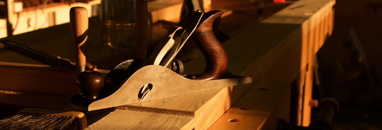
Here you can see the array of planes used the create the moulding.

IMG_2235IMG_2203IMG_2201IMG_2200IMG_2202

I then moved on to seating the twin screw vise stand offs. The 30 mm diameter holes meant to accept the ACME threaded rod were already drilled through the top a week or so ago. I used an electric hand drill with a spade bit to remove the bulk of the waste before chopping the rest out with my Lie-Nielsen ½” mortise chisel.

IMG_2182IMG_2183IMG_2185IMG_2193IMG_2192IMG_2194IMG_2197IMG_2205IMG_2206

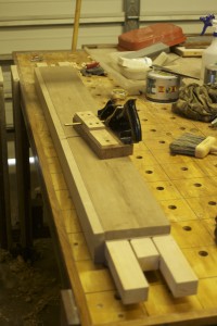
That got me this far.

IMG_2210IMG_2209

The electric router removed most of the waste for the shoulders (so to speak) of the stand offs. I then used the router plane pictured to dial it in to the exact depth.

IMG_2213IMG_2214IMG_2215IMG_2218IMG_2217IMG_2222


IMG_2221IMG_2226

The result.

IMG_2223IMG_2225IMG_2227


Next I marked out and drilled the holdfast holes in the legs on the drill press. You will notice that the ¾” holes are relieved to 1″ from the back of the leg.

IMG_2229IMG_2230IMG_2231IMG_2232

IMG_2233

Replacing Lie-Nielsen mortise chisel handle

8/9/2014

A few weeks ago the original Hornbeam handle of my ½” Lie-Nielsen mortise chisel expired as pictured. Being smashed constantly with a shop made Ysterhout mallet does not seem to agree with Hornbeam’s constitution. Ysterhout (Olea capensis macrocarpa) at a Janka side hardness of 10,050–13,750 N and Janka end hardness of 9780–14,200 N makes Hornbeam feel like a marshmallow. It thus made sense to turn the new handle out of Ysterhout, which I duly did.

I quote from a bit of interesting info on this species for you from the website indicated below.

Uses and cultural aspects
An authoritative source (Mabberley, 2008) informs us that ironwoods have the heaviest known timber, with a recorded specific gravity of 1.49. In other words, the timber of these trees sinks like a stone when put into water. Ironwood timber has long been respected, but its weight and hardness have to some extent limited its popularity, and it is not as widely encountered in antique furniture as, say, stinkwood, yellowwood or Indian teak. However, Hartwig (1973) reports the existence of antique ploughs and harrows made at least partly of ironwood. The limited use implied by Hartwig fits well with Von Breitenbach’s (1974) observation that the early foresters left a disproportionate number of large black ironwood trees standing, because with only hand-powered tools, it was much more profitable to go after yellowwood and stinkwood – for the effort involved in felling and removing one ironwood, they could process several of the other trees. Nonetheless, Von Breitenbach reports that the wood is suitable for sleepers, piles, flooring and veneers. One can imagine that the objection to making furniture out of the solid wood is that the results would be so heavy as to be almost immovable. The use of these trees for firewood, and (while living) for shelterbelts and as ornamentals is recorded.

http://www.plantzafrica.com/plantnop/oleacapensis.htm

IMG_2180IMG_2181


I though I would turn two while I am at it.

IMG_2156IMG_2167

Straight after being seated.

IMG_2168IMG_2169


15/9/2014

After a bit of pounding.

IMG_2177IMG_2178IMG_2179


My 18th Century Workbench in progress 19

8/9/2014

At this stage it was back to the drill press to remove some waste from the mortises before butchering the rest away by means of a mortise chisel and mallet madness.

IMG_2086IMG_2087IMG_2088

I used my Festool router to cut the dado in which the top of the deadman will slide. The same router were then employed to cut the dadoes in which the tool trays will slide between the two parts of the twin-top.

IMG_2109IMG_2110IMG_2111IMG_2112IMG_2113IMG_2114IMG_2115IMG_2117IMG_2116IMG_2118IMG_2120IMG_2121IMG_2122IMG_2123

As per usual I flattened one side of the beech boards destined to become the twin screw vise chop with hand planes, removed the twist and finished the job off with the planer. They were then clamped to the assembly table and left to settle for a few days while I continue with other bits and pieces.

IMG_2124IMG_2125IMG_2133IMG_2134

One such task is painting the Irwin quick release vise black as it’s traditional blue does not fit into my idea of je ne sais quoi.

IMG_2131IMG_2132

Shop made pairing handle for my Lie-Nielsen bevel edge chisels

8/9/2014

This past weekend I had to replace the chopping handle of my Lie-Nielsen mortise chisel, as the Hornbeam original succumbed to hours of relentless pounding with my Ysterhout mallet. While I was doing this I thought it would be a good idea to also turn a longer Ysterhout handle for pairing purposes. You can see what it looks like in the pictures below. I can now use it on all my Lie-Nielsen bevel edge chisels to convert them into pairing chisels in no time.

IMG_2170IMG_2171IMG_2172IMG_2173

My 18th Century Workbench in progress 18

27/8/2014

Last night I sat down to design the chop of the leg vise. I wanted to come up with something fresh that I have not seen before, yet without compromising on the function of the chop. The pictures below show my freehand concept sketches. You will have to wait until we build the chop to see how we create this appearance. I still do not know myself, but time will tell. I will add the photos of how the chop develops to this post as it happens.

IMG_0159IMG_0160


8/9/2014

Here you can see how I processed some beech using my band saw and planer. I am aiming for a chop that is about 2″ thick after laminating these strips.

IMG_2089IMG_2090IMG_2091IMG_2092IMG_2093IMG_2094

In order to lose as little thickness as possible I hand planed one edge of each strip flat and used that as a reference surface to guide my Festool Domino. The dominos help to keep the reference edges flush during the glue-up.

IMG_2095IMG_2096IMG_2097

I arranged the strips as pictured with attention to it’s end grain.

IMG_2098IMG_2099


In these pictures you can see how my assembly table and a few clamps assisted to hold the strips while cutting the domino slots.

IMG_2100IMG_2101IMG_2102IMG_2103


My skill to and method of lamination has improved significantly as a result of the shear volume of lamination required during this project. I use my shop made proletarian sanding contrivances loaded with a range of different grit sandpaper (120, 150, and finally 240) to remove machine marks from the glue surfaces.

IMG_2105IMG_2107IMG_2106IMG_2104IMG_2108IMG_2126IMG_2128


After flattening one face of the laminated stock with a range of hand planes it was used as a reference surface in the planer to flatten the opposite face. I then marked out the curves, drilled the holes for the vise screw etc etc.

IMG_2135IMG_2136IMG_2137IMG_2139IMG_2140IMG_2138IMG_2141


Here I removed the bandsaw ripples with my Lie-Nielsen block plane followed by some attention from the proletarian sanding contrivances (aka sanding planes).

IMG_2142IMG_2143IMG_2144


Then I started shaping the chop as pictured using my late 19th century Buck Bros. drawknife followed by a series of rasps and files.

IMG_2145IMG_2146IMG_2147IMG_2148IMG_2149IMG_2150IMG_2151IMG_2152IMG_2153IMG_2154


6/10/2014

IMG_2291IMG_2292IMG_2293IMG_2294IMG_2349


3/11/2014

A quick dry fit with the bench assembled.

IMG_2574IMG_2575IMG_2576

Here I prepared the tenon for its two wedges.

IMG_2579

I shaped the top of the jaw at an angle. I thought I would first use the vise for a while, before trimming it flush to the top of the bench. That way it has some time to settle.

IMG_2580IMG_2581IMG_2582IMG_2583IMG_2584

The toe was shaped as pictured.

IMG_2588IMG_2589

I chose Namibian Skeleton Coast seal bull leather to add grip to my leg vise. It is incredibly tough stuff.

IMG_2585IMG_2586IMG_2590IMG_2591IMG_2592IMG_2593

This is officially my first attempt at carving.

IMG_2594IMG_2595

The chop was glued into position using the pictured method to ensure that it is lined up absolutely spot on.

IMG_2600IMG_2601IMG_2602IMG_2603IMG_2604IMG_2605IMG_2606IMG_2607

Now this next process took some time to find a solution for. I decided to add leather to the leg as well, but wanted it to remain flush with the rest of the front of the bench. Therefore I needed to remove wood (about ¾ of the thickness of the leather) in the area where the vise jaw touch the bench and leg. It was quite a mission, but I finally managed to do it with the help of my router plane.

IMG_2596IMG_2597IMG_2608IMG_2609IMG_2610IMG_2611IMG_2612IMG_2613IMG_2614


This way the leather becomes flush with the front of the bench once some pressure is applied by the jaw. So far so good.

IMG_2627IMG_2632