13/8/2013
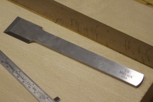
The third plane I prioritised to build was a shoulder plane. As per usual I decided to use a Lie-Nielsen blade in the form of their Large Shoulder Plane replacement blade. As you can see in the pictures below it is a blade that is designed to be used bevel up, given the bevels on the sides of the top of the bit end. I did not really grasp this until it was pointed out to me by Deneb Puchalski from Lie-Nielsen. I actually planed to bed the blade at 50-55º and use it bevel down. He advised me to consider a much lower bedding angle while using the blade bevel up.
I then started thinking of a way to change the design quite radically from the examples I found in my research. You will have to wait and see how it turns out as I myself still does not know exactly what the final design will look like. I will again (similar to what I did with the Scrub Plane) write this post as I progress with the project.
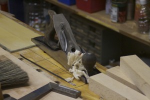
In the pictures below you can see the beech I used for the project and the Lie-Nielsen blade.

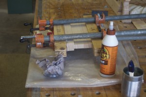
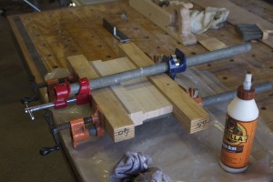
As with the other planes I have built so far I had to laminate in order to get the size stock required. I laminated it in this particular orientation to ensure that I have the grain running in the direction recommended by the guys from Old Street Tools. I can really recommend their articles (which is available for free download from their site) on plane building. You will find the the link to their site on the library page of this site.
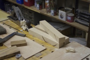
The lamination process. You will notice the use of my glue roller. I wrote a separate post on how I made this tool, which you will find under the category “Hand tools”
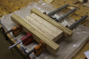
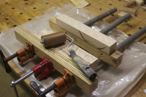
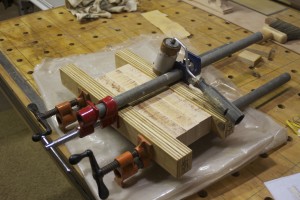
The beech blank.


I used the actual blade to mark out the next step of cutting away the sides …
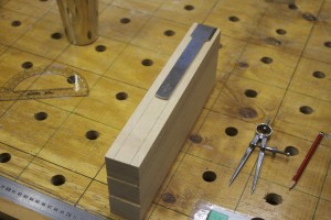
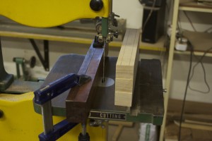
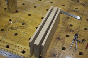
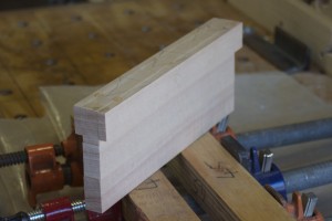
… as so. In the last of the three pictures you can see the strips I ripped off the sides, which were then glued back on the centre piece.
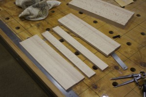
Before glueing the strips back I first fed the inside to the thicknesser to get it down to about 2 mm wider than the tang of the blade.
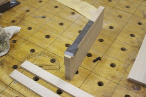

The strips were then hand planed to improve the contact during glueing.

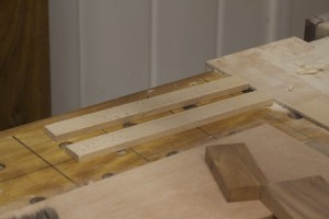
Dry-fit and glue.


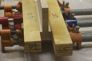
Here you can see how I removed the hardened glue with my shop-made flush plane before hand planing the sole in preparation for the glueing on of the ysterhout sole.
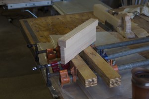

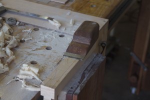
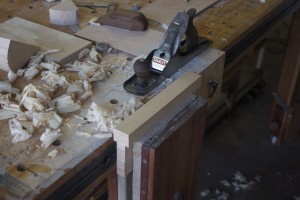

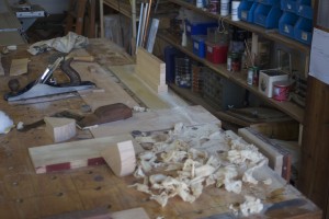


Glueing on the ysterhout sole.

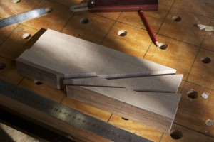
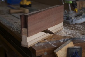
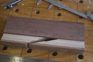
I then used my bandsaw Mitre-sled to cut a 20 º bedding angle for the blade and 12º space for the wedge.

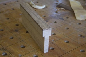


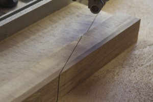

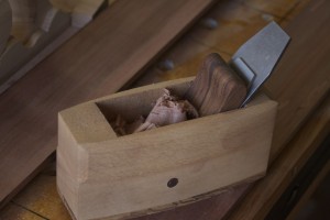
Up until this stage the design I was aiming for looked like the one below …

… but I realised that the small triangular area on the “bedding piece” available as a glueing surface for the kershout sides (still to be made), would not be adequate. I therefore dropped the project and continued with the four other planes (Jack, Fore, Smoothing planes and a jointer) I started working on.
1/10/2013
During a trip to Cape Town recently to go and what the Springboks butcher the Ozzies, I had some time to think on the plane (that is thinking on the airplane about the shoulder plane) and came up with an idea of how to hopefully make this plane work. As I am writing this I still have no idea if it would work as it entails quite a few tasks that I have never attempted before.
Anyway, I got back on the horse and took some beautiful kershout from this massive board. A Kershout tree of this size would have been between 700 – 1000 years old if my friend who studied these things knows anything.
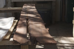


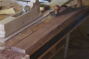
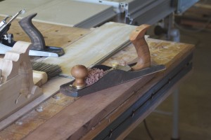
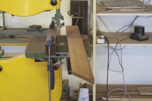
I re-sawed the piece on the bandsaw and tidied it up with the thicknesser and hand planes.
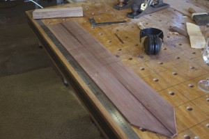
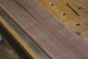
Here you can see my delightful petite smoothing plane in action. I wrote an entire post on how I built it a few months ago (http://www.jenesaisquoiwoodworking.com/petite-wooden-smoothing-plane/)
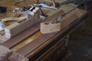
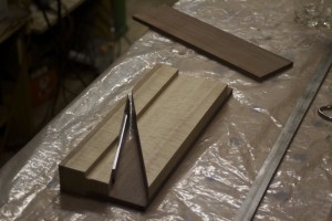
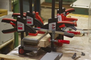
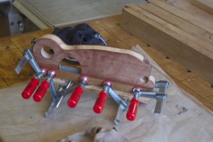
The plane was then glued together. In the first picture below you can see an unpolished piece of stainless steel, which is integral to the success (hopefully at this stage) of my new idea.
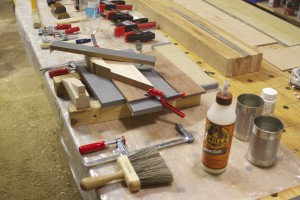
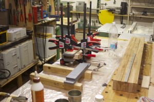
7/10/2013 – I released the plane from the clamps on Friday afternoon and spent an hour playing around with various shapes and designs based on an idea I had. Finally I came up with the design as drawn on the blank before heading down to our Barbie area to light a fire and drink a few cold beverages.
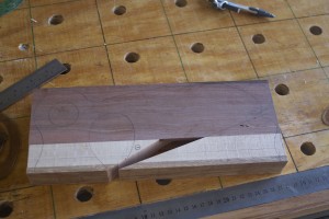
On Saturday morning I started to shape the plane in order to be able to epoxy these strips of stainless steel in place so that it could set well overnight.
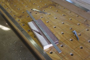
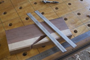
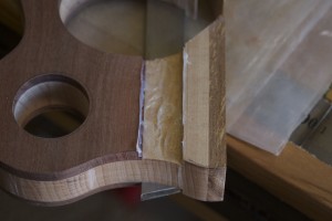
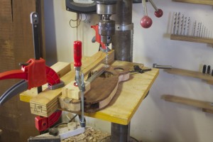
You can see how I made a few test cuts in a scrap piece of plywood to ensure the absolute correct depth of cut for the dado meant to accept the stainless steel. I used my removable pipe-clamp-end-vise to keep the plane in position for cutting the dado.
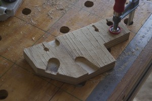

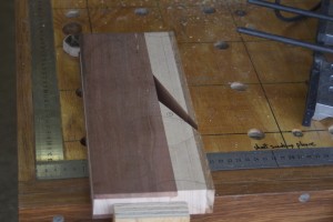
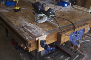

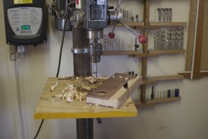
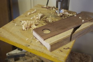
The two dados meant to accept the two stales steel bars is clearly visible in the first two pictures. I then proceeded to shape the rest of the plane by drilling out certain areas an using the bandsaw for the rest.
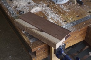
The next step was to epoxy the stainless steel into place.
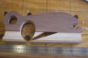

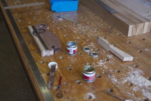

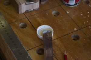
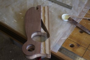
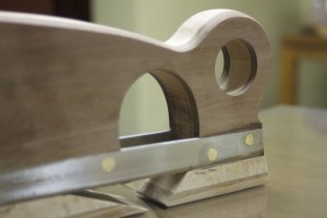
The next day I drilled out six holes through the stainless steel from side to side. These holes were 6 mm in diameter with the entrance chamfered slightly, as you can see. I made six pins out of 6 mm brass rod that was about 5 mm longer than the width of the plane and whacked it through the holes with equal amounts protruding at each end.



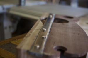
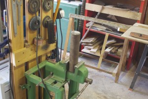
I used the setup below to rest one of the protruding ends on while whacking the other with a hammer until the brass moved into the chamfered area and fixing the stainless steel into this position for ever.

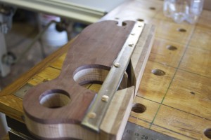
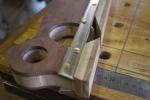
As you can see in the pictures below, I then removed the untidy excess metal and polished it as best as I can given my lack of metal working tools and skills.
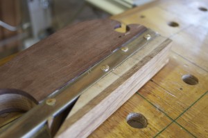
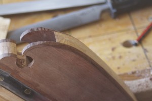
Then came the long hard slog of shaping the edges of the plane using a block plane, a spokeshave, and several files.


Sides were tidied up with my shop made proletarian sanding contrivances.


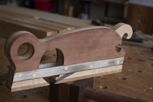
At present the plane looks like this. Next I have to make the wedge and am considering to try some decorative coloured epoxy inlays, but let’s see what happens.
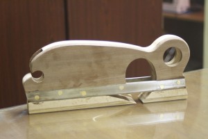
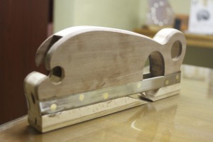
13/10/13 – On Friday afternoon I quickly fashioned this wedge out of beech.

On Saturday I changed the shape ever so slightly as you can see here. The blade will be set by a special plane hammer with a delicate neck, which I still have to build.

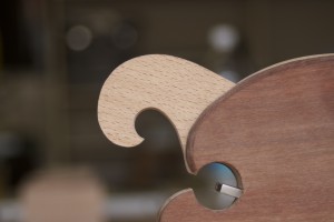
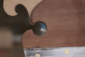

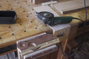
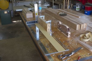
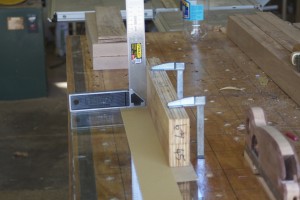
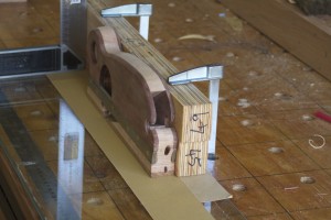
The next step was to ensure that the sole of the plane is 100% square with the left cheek. As a right-hander I would use the plane predominantly with the left cheek as reference surface. I used the setup as shown to sand the sole square.
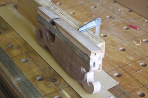

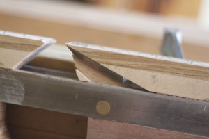
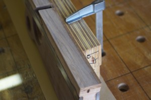


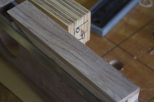
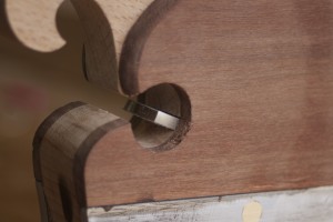
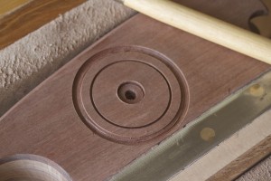
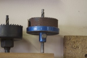
As discussed in one of the “My journey” posts, I am using this tool building phase to try out and practice techniques that might come in handy when I start building furniture. Here I thought of trying-out coloured epoxy inlaying to add some je ne sais quoi to the shoulder plane. I used the drill bit pictured to create the grooves and tidied it up with a carving tool.

As you can see, I mixed some epoxy with acrylic paint …
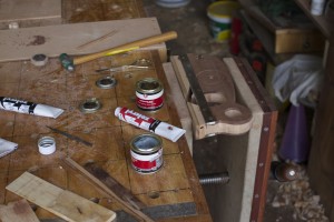
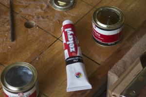
… and used small scrap bits of wood as spatulas to work the mixture into the grooves. After a few hours I used my shop made flush plane to cut most of the excess away before the epoxy became too hard. It is a shlep to sand it away once it becomes rocklike.

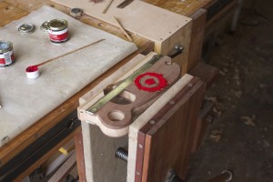

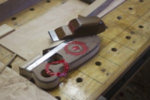
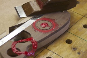
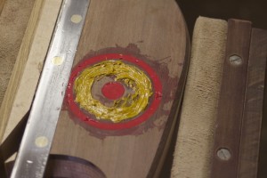
I then used my proletarian sanding contrivances to sand away the last little bit of epoxy and started the finishing process as shown.
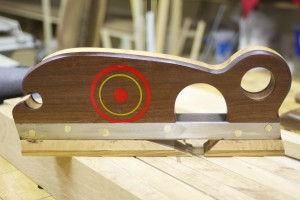
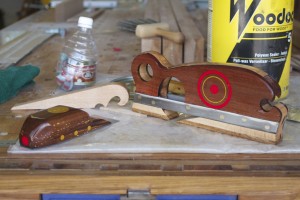
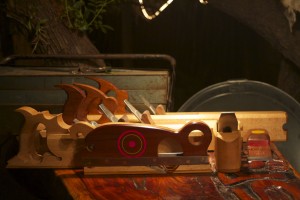
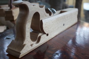
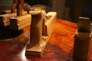
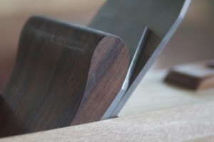
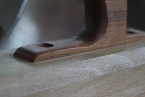
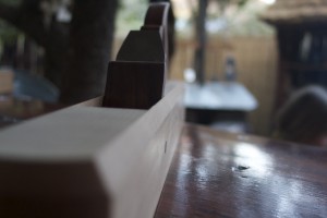
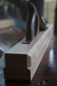
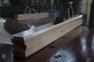
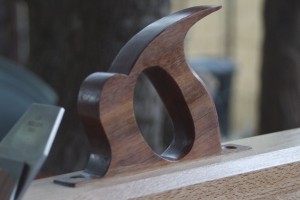
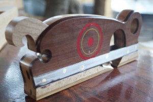
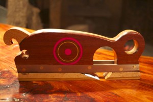
Here are a few pictures of the finished shoulder plane. Now I only have to sharpen the blade and Bob’s your uncle. The blade is bedded at 20º with a 25º primary bevel. I am planning to hone and polish a small secondary bevel at 28º, producing a 48º effective angle of attack.
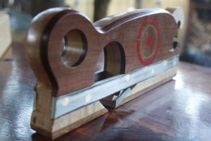

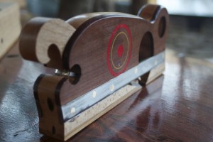



Like this:
Like Loading...
