Old Stanley Bailey handplane rehabilitation

My father gave me most of his tools some years ago when he decided to downscale and pursue other interests. He was very much a powertool woodworker as apposed to a hybrid woodworker (someone who uses both hand tools and power tools) or a handtool woodworker. I never even knew that he was as his way was the only way I knew, until I started reading American woodworking magazines and listening to podcasts such as the one by the Modern Woodworkers Association (my favourite) and Wood Talk (highly recommended). Now I realise that there are other ways to approach woodworking conundrums.

It is not as if I am not grateful for everything I learnt from my Dad, as it certainly got me hooked to woodworking in a big way, but I am finding myself gravitating towards quality handtools with a vengeance. I guess that would make me a hybrid woodworker with fairly basic handtool skills at present.

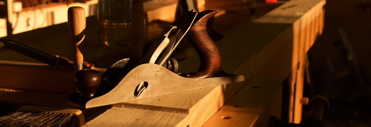
This is really a roundabout way to get onto the primary purpose of this post, which is the rehabilitation of the two old Bailey handplanes my Dad handed down to me. It is a no. 4 Smoothing Plane and no.5 Jack Plane that really needed serious attention. I never even knew that one should sharpen the plane irons as my father and I never did. Probably, in hind sight, because we never used them. For this reason they never seem to work very well, which did not encourage any further scrutiny.

That was until I watched the DVD on Plane Sharpening by David Charlesworth and using a sharp Lie-Nielsen No.4½ Smoother. It would not be too much of an exaggeration to say that it was an epiphany. A sharp handplane is poetry in motion. It is psychotherapy for a shrink … literally in my case. David also explains very clearly in his DVD what comprises a functional and well tuned (apart from a sharp iron) handplane, which is all very useful to any woodworker, but especially to plane rehabilitators.

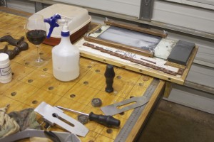
Armed with this new knowledge I set about to rehabilitate these family heirlooms. In the first few pictures you can get an idea of the state they were in. It used to be toilsome to slice Parmesan cheese with these planes, to be honest.

100_1202100_1203100_1204IMG_6814

First step was to flatten the soles of these planes and it turned out that they were in some serious need of this particular ministration. An added bonus of doing this is that it makes the shiny parts of the plane body smile with a rewarding gleam. I have to warn you that this is hard work that can take time and perseverance from a woodworker. You do not have to get it 100%, but the toe, the area behind the mouth and a reasonably large area towards or at the heel all needs to be in the same plane.

A Magic Marker is very useful to demonstrate the areas that needs attention. Drawing a grid (as shown) before taking a few swipes over wet-and-dry-sandpaper fixed to 10 mm thick float glass, would reveal the troublesome spots in no time. Please note that I left the plane irons clamped in their usual position, only making sure that they are retracted well into the plane body in order not to get damaged by the flattening activity. The reason behind this is that the clamping action of the lever cap deforms the sole ever so slightly which means that you want to flatten it while under tension.

IMG_6812IMG_6813

The remnants of gridlines clearly indicate the low lying areas as seen below.

IMG_6815IMG_6816IMG_6817

Then it becomes a question of elbow grease, burning some midnight oil or whatever it might be called. Here you can see how I used my sharpening jig to do the flattening. If you want to read the post on how I made this jig find the post called “My version of Deneb’s sharpening jig” under the category “Jigs”. This jig clamps wet-and-dry sandpaper on a piece of float glass by means of two cauls.

IMG_6818IMG_6819IMG_6820IMG_6821IMG_6822

The final product is well worth the effort I thought.

IMG_6823

Next I took the planes apart completely, including removing the plane irons with their chipbreakers, the frogs, the totes and knobs.

IMG_6824IMG_6825IMG_6826IMG_6827IMG_6829

Here you can see how I sharpened the new replacement blades I bought from Lie-Nielsen. If you are interested in purchasing replacement blades for old Stanleys, check out Lie-Nielsen’s website, they have the whole range. Their blades are definitely the business. Their blades are prepared at a primary bevel angle of 25º and ground flat as … oh no just remembered this is a family website … but you really do not have to do too much work on the back at all.

I honed a 33° honing angle on my 1000 grid Ohishi waterstone and polished a 35º final cutting angle on a 10 000 grid Ohishi stone. Both blades were sharpened with a cambered edge.

Blade bevels.Blade bevels 2.IMG_6830IMG_6831IMG_6832IMG_6869IMG_6870

In the picture below you can see the Nagura stone I use with the 10 000 grid stone.

IMG_6835

Here you can see how the totes and knobs looked like prior to rehabilitation. Clearly some type of varnish left that was starting to look seriously weathered. I removed the the varnish with a card scraper before tidying it up with sandpaper.

IMG_6836IMG_6837IMG_6838IMG_6840

A last picture before the frogs came off.

IMG_6841

The two screws that fix the frog to the body of the plane is evident in the first picture. In the third picture you can see the screw that helps you position the frog during reassembly depending on how tight you want the throat.

IMG_6842IMG_6843IMG_6845

Next step was to carefully remove the worst of the rust from the frog’s surface that supports the blade with a fine flat file.

IMG_6846IMG_6848IMG_6849IMG_6850

In the first picture below you can see how I then used a magic marker to blacken all the surfaces that is in contact with the back of the blade. In the next picture you can see the setup I used with 150 grid wet-and-dry sandpaper on a piece of float glass on the edge of the table in order to easily hone the most important front section of the frog. In the third picture you can see how the leftover magic marker indicates the areas that needs more attention after just a few strokes on the sandpaper. The last picture show how it is all cleaned up and flat as … yes you know what I mean.

IMG_6851IMG_6852IMG_6853IMG_6855

Here you can see how I cleaned up and flattened the areas of the frog that is in contact with the plane body.

IMG_6856

Speaking of plane bodies, here you can see how they look prior to a Ballistol treatment.

IMG_6857

One of the most important parts of this rehabilitation operation is the work done on the chipbreakers. You want to flatten the area in contact with the blade at an angle that will ensure that the absolute tip of the chipbreaker sits flat on the back of the blade. This is accomplished by the setup as shown. You can see how the angle created will ensure that only the tip ends up flat on the blade.

IMG_6861IMG_6858IMG_6859

Here you can see how I decreased the angle slightly for honing and polishing. In the last picture you might be able to appreciate the perfectly polished and flat area that will ultimately sit on the back of the blade.

IMG_6863IMG_6864IMG_6862

The lever cap being made of cast iron is much easier to flatten, but again remember to set it up so that you only flatten the area that matters at the very tip that will be in contact with the chipbreaker. These lever caps were not even close to flat in the mentioned area.

IMG_6865IMG_6866

Here you can see the totes and knobs before and after a Ballistol treatment.

IMG_6867

Both totes were very wobbly due to very slack tolerance around the two raised cast iron areas on the base. I decided to remedy this by inserting some Epoxy putty and squeeze the tote into position, in order to create a perfect fit.

IMG_6871IMG_6872IMG_6873IMG_6874IMG_6875IMG_6877

Finally all the parts were reassembled with the frogs set up to create a very tight throat on both planes. I can really recommend doing this for those of you who do not mind some elbow grease in return for a pleasing precision tool. There can be no comparison between how these planes cut post rehabilitation compared with prior to it. It is an absolute pleasure.

IMG_6878IMG_6879IMG_6880IMG_6881IMG_6882IMG_6883


As per usual, the proof is in the pudding. Here are some of the first shavings I took. It is poetry, I tell you!

IMG_7096

I think they are ready for another few hundred years of work.

22/4/2014

IMG_0187IMG_0188IMG_0191IMG_0192IMG_0193

Shop humidity

On the podcasts I listen to the guys often refer to the ambient humidity in their shops. Namibia being a fairly dry country, but with a definitive rainy season would have quite a dramatic shift in humidity between summer and winter I thought. The question is how much and exactly what is happening in my shop?

The reason why I first thought about recording this was when I heard this one guy (can not remember who) suggest that one should consider building one wooden plane for winter and one for summer to cut down on the amount of tuning that needs to be done secondary to wood movement. I am currently in the process of research and information collection before embarking upon a wooden plane building spree.

I thought I should therefore start to collect data on the changes in humidity in my shop. In the pictures below you will see the small electronic device I use to record the temperature and humidity. It is able to record the current, maximum and minimum for both humidity and temperature.

I record the maximum and minimum each time I am in the shop on the chart pictured. Once in a while I would then enter this data into a database I have built using Filemaker. The database then calculates the averages for whatever time frame you are interested in, be that a month, a season or a year. Of course I first need to collect a year’s data to do the latter.

IMG_6783IMG_6781IMG_6780IMG_6782

Temperatue and humidity chart


I might write a very brief post from time to time reporting on the actual humidity trends in the shop. So far I found the following:

March 2013 – Average Minimum Temperature 24.7°C Average Maximum Temperature 30.2°C Average Minimum Humidity 21.5% Average Maximum Humidity 34.4%

April 2013 – Average Minimum Temperature 17.9°C Average Maximum Temperature 25.6°C Average Minimum Humidity 29.6% Average Maximum Humidity 44.3%

May 2013 – Average Minimum Temperature 15.6°C Average Maximum Temperature 22.5°C Average Minimum Humidity 28.4% Average Maximum Humidity 36%

15/1/2015

I did not manage to record any data in 2014, so one of my New Year’s Resolutions is to get back into the habit. I did however manage to enter the data for the rest of 2013 in order to calculate the averages.

June 2013 – Average Minimum Temperature 12.4°C Average Maximum Temperature 18.6°C Average Minimum Humidity 31.3% Average Maximum Humidity 35.6%

July 2013 – Average Minimum Temperature 11.7°C Average Maximum Temperature 19.5°C Average Minimum Humidity 31% Average Maximum Humidity 35.5%

August 2013 – Average Minimum Temperature 13°C Average Maximum Temperature 22.2°C Average Minimum Humidity 28.2% Average Maximum Humidity 34.7%

September 2013 – Average Minimum Temperature 14.7°C Average Maximum Temperature 25°C Average Minimum Humidity 28.1% Average Maximum Humidity 39.9%

October 2013 – Average Minimum Temperature 21°C Average Maximum Temperature 29°C Average Minimum Humidity 23.3% Average Maximum Humidity 31.2%

November 2013 – Average Minimum Temperature 22.1°C Average Maximum Temperature 30.6°C Average Minimum Humidity 23.2% Average Maximum Humidity 37.1%

Alternative workbench/assembly table (Chapter five)

Finally, we embark upon the last stage of this adventure in looking at the chop (of the quick-release-vise), how the top was finished and a few examples of how the table assists with work holding. You will remember that work holding ability was one of the primary objectives behind the design of this table. The chapter concludes with a bit of a postmortem.

In the pictures below you can see how I put the chop of the quick-release-vise together. Again I used Ysterhout and created 4 square dogholes. In hind sight I made a mistake by laminating the pieces of wood between the doghole cross-grain to the rest. Since I made this chop-face the wood has moved enough to create approximately 2 mm difference at the top as well as the bottom, after starting off flush. This should not have been a surprise, but served as a useful reminder why it is generally discouraged. It does however not cause any functional limitations, but will probably lead to an immature demise of the chop. Time will tell.

100_0177100_0178

100_0180

Here you can see how I flattened the face of the chop with a belt sander. I did not have anything better for the job at the time. The wood is simply too hard for a normal handplane and I still did not have my Lie-Nielsen babies back then. Even the Lie-Nielsen’s at a bedding angle of 50° (York pitch) reject this wood as unpalatable.

100_0194100_0197

Here I added purely cosmetic parts to the chop.

100_0212100_0234

Initial shaping of the chop-face on the table saw.

100_0241

A quick dry fit before final shaping, with my son Didi acting as model together with our German Shorthaired Pointer called Nietzsche. Didi is doing his rendition of O-Ren Ishii (aka Cottonmouth) in Kill Bill.

100_0242100_0243100_0244100_0245

All the Ysterhout edges were fixed to the top standing proud by a millimeter or so. In the next pictures you can see how I brought everything into one plane by careful belt sanding. I know this is a kak idea, but I honestly did not have another option at the time. The second picture does at least show that I got it reasonably flat.

100_0237100_0238100_0239

The next step was to glue in the steel ruler on two sides of the table. Although the ruler stop inside the Ysterhout edge, I set it up (by carefully removing the correct amount) so that the ruler show the measurement as of from the edge. This way I can have a stop flush with the edge, push a piece of stock against it and very quickly read the length or mark a measurement on it without having to fiddle with a tape-measure. You will remember how we recessed this area of the bench to ensure that the ruler sits flush with the top.

100_0247100_0248100_0251100_0249

Then I started drawing lines corresponding to each 10 cm on the rulers. Every second line being green and the ones in between black. This makes it easy to count in 20 cm steps. The lines are square to the sides of the table and each other, which makes it easy to set up square guides for gluing panels.

100_0255100_0256

The plywood part of the top was then sealed with floor varnish in order to have a fairly hardwearing surface that is easy to clean when wood glue is spilled on it.

100_0257100_0258

All the Ysterhout edges were treated with something called Woodoc, which as a local product that probably contains a mixture of oils. I assume it must be something like dried Linseed and/or Tung oil because it dries to a film on top of the wood after a few layers, but is easy remove or touch up if necessary. It certainly liberates the shear beauty of the Ysterhout.

100_0271100_0287100_0288100_0289

… and voilà … the final product for your perusal!!!

100_0285100_0293

Here you can see where my benchdogs live. If you are interested to see how I made these, please please the post on Bench Bitches under the category Bench accessories.

100_0303

I though I should include a few pictures illustrating how the bench assists with work holding.

100_0575100_0876100_0875100_0884100_0885100_0890100_0859


In the next few pictures you can see how the T-channel (which can be accessed through any of the  round access points rather than only the ends, as seen in the second picture) and benchdogs work in tandem to hold the two wide plane-stops in place for hand planing.

DSC03191DSC03192DSC03193

This was an immensely satisfying project, the result of which really improves the quality of my work and the amount of pleasure I get out of spending time in the shop. Having said that, I think it is important to always think about how one could improve your work. Therefore I thought it might be useful to consider what I have learnt while building and using this table.

The main problem I have found so far has to do with the table’s overhanging edges. I other words, not having legs in the same plane as the edge of the table. This combined with the fact that the table’s main frame is made out of steel rather than wood combines to create a less solid and noisy surface when using a chisel and mallet to chop mortises for example. Even at the top of the leg it does not feel or sound as good as on a proper wooden bench with massive wooden legs. I would not change the design of the table because of this, as the ultimate objective with this table is to have a dedicated assembly table and for such a table it is much better to have the legs out of the way to improve the ease of movement around it. It might actually help someone else building a similar table to consider different options depending on their needs. I have to bear with this shortfall until I build my dedicated bench.

The next thing I have noticed is that my table is a bit too high for hand planing. Again this would not necessarily change my design as I am currently bound by the height of my table saw as this assembly table doubles up as an out-feed table. It did however help me to understand what the people who knows are on about regarding this issue. When the table is too high you end up using your arms more than your legs, which means that your control deteriorates and you get tired much quicker. I can really recommend Christopher Schwarz’s discussion on this in his book “Workbenches: from design & theory to construction & use”.

The next issue would actually change how I do it if I had to do it again. Given that I am using it as a workbench in the interim, I think I should have used proper wood for the top rather than plywood. I would also increase the thickness of the top while doing so.

Finally, I think I should have borrowed a router (as I did not have one at the time) to do the dogholes with. That would have done a much better job in terms of getting the holes 100% square to the working surface.

I do hope that someone will be able to learn something from this or at least get a few ideas for their own table/bench.


It’s a dowel plate mate

This is another brief post explaining how to make a very handy hand tool in no time. If you are in need of custom made dowels, this is a very useful tool. As usual I got this idea from Lie-Nielsen.

All you need is a scrap piece of steel. I took this chunk of steel left over from another project and drilled 5 holes starting at 10 mm increasing by 0.5 mm at a time up to 12 mm.

100_0553

100_0555


The idea is to cut square strips of wood slightly bigger than needed, shape it a smidgen with a plane …

100_0554100_0556100_0557


… and tap it through the holes, starting with the biggest that would accept the blank and moving down to the size intended. In the pictures below you can see how I made the dowels for my mallet. If you want to know more about the process of building the mallet, see the post titled “Mallet Mania”.

100_0558IMG_5670IMG_5672


… and voilà, some custom Witpeer dowels!!!


100_0559


Legvise with a twist (Chapter two)

As promised, we will start looking at what makes this legvise different to others in this chapter. For one thing, I do not know of any legvise that sports an Ysterhout parallel guide. If you are interested you could read more about Ysterhout’s properties in my post on my assembly table. (www.jenesaisquoiwoodworking.com/alternative-workbenchassembly-table-chapter-four)

This process might well seem a smidgen confusing, but I show the process as close as possible to how it happened. It means that various parts gets worked on all at the same time and we discuss only the small step that was taken at that time then jump to the next part and return to the previous part at some point in the future. If you do woodwork I am sure you will understand this haphazard methodology.

In the pictures below you can see how I laminated two pieces of ysterhout to create the beginning of a parallel guide.

100_0371100_0374

The area I removed here was done on the table saw. The idea was to use this design to provide ample structural strength to the joint with the chop (moving jaw of the legvise). As I see it this is a critical joint that will have to endure innumerable years of abuse.

100_0401100_0403100_0402

At about this point in time, my first acquisition from Lie-Nielsen arrived, a large vise screw.

100_0372100_0375

Now we can start to address were this legvise really departs from the norm. As I explained extensively in my post on the assembly table, I opted to modify an assembly table to double up as a workbench until I know what I want from a workbench. My assembly table does not have massive wooden legs that are in the same plane as the top. Therefore the first difference is that the inside jaw of my legvise had to be made, so you could actually argue that it is not a legvise because it does not contain a leg?? You would have noticed the two jaws being assembled in chapter one.

The next problem involves my assembly table’s ability to be adjusted up and down. (see Alternative Workbench/assembly table chapter two) This necessitated my ‘freestanding’ legvise also to be able to do this. In the pictures below you can see how I approached this issue. The inside jaw (or “leg”) of my legvise was modified to accept two pieces of 20 mm threaded rod, that would become the adjustable “feet” by fitting two nuts as shown. It will become clearer as we progress.

100_0383100_0385100_0384

I then cut the mortise intended to accept the parallel guide at the bottom the chop. Next I created the “hole” (it would only become a hole a little later in actual fact) through which the parallel guide moves in the “leg”.

100_0503100_0504100_0492100_0494

A quick dry fit to check how the parallel guide fits in it’s mortise at the bottom of the chop.

100_0490100_0491100_0489100_0505

Please note the makeshift fence to ensure that the holes in the parallel guide are well aligned. I had to drill these holes spread across three evenings as a result of the incredibly dense Ysterhout. Directly translated “ysterhout” means “ironwood” and it really is very similar to drilling holes in steel. The bits heats up with a vengeance, necessitating a substantial break before continuing or alternatively destroying the bit.

100_0591100_0592100_0633100_0634

Next I added (by means of PVA glue) the top and bottom of the inside jaw. The top will ultimately help to fix the inside jaw to the table and the bottom will create a surface to attach one of the rollers guiding the parallel guide. Just bear with me, it will all become as clear as daylight in the next riveting chapter.

100_0513100_0515

At this stage the final shaping took place. You obviously expected the je ne sais quoi to emerge at some stage didn’t you? The sexy symmetrical sloping semblance certainly adds you know what.

100_0549100_0550

Cutting thin Kershout and Witpeer strips on the table saw is not a good idea. You can probably see the burn marks in the first picture. I laminated some of these strips to create a blank to turn a bootylicious handle for the vise.

100_0653100_0679100_0680100_0722

The mentioned handle being shaped and turned.

100_0723100_0724100_0824

Finally the hole meant to allow the Parallel guide to extend through the inside jaw gets completed.

100_1085100_1086100_1087100_1088

In the pictures below you can see how the nuts that are supposed to accept the threaded rod feet gets locked into position by a thin Assegaai lid.

100_1089100_1090100_1091


In the last chapter we will discuss the final months of my the legvise pregnancy. Jippee ki-yay … as they say!!!

Card scraper holder

This is a quick post showing an easy way to store your card scrapers so that they become very accessible. Until I made this high-tech holder my card scrapers were hiding in a leather wallet type of thing. That old saying that goes “out of sight out of mind”, applied and I often forgot that these handy tools would be idea for a particular job.

In the pictures you can see my set of Lie-Nielsen scrapers resting on the leather pouch while dreaming about their new luxurious abode. I took a piece of laminated Asseggai/Witpeer left over from my legvise project and tidied it up somewhat. In order to cut really thin curves to ensure that the scrapers will not wobble too much, I used this as a hand sawing exercise. My Lie-Nielsen carcass saw cuts a very thin curve, which only accepted the thin scrapers not the thicker versions.

IMG_6733IMG_6734

My custom made Tamboti marking knife came in handy to mark out the cuts. (Please see www.jenesaisquoiwoodworking.com/tamboti-and-witels-marking-knives if you want to read the post on how I made the marking knife) I left the rest of the block of wood untouched for now. It might become the home of scrapers of different shapes that I still plan to make once I find a suitable piece of steel, like an old saw blade.

IMG_6735IMG_6736

You can see how I practiced the skill of sawing to a line using a benchhook.

IMG_6737IMG_6738IMG_6739

The results for all to see. It is certainly not perfect but good enough for this purpose and gave me a bit of practice.

IMG_6740IMG_6741IMG_6742

As usual the product was finished off with some Ballistol and Bob’s your Uncle.

IMG_6743IMG_6745

Alternative workbench/assembly table (Chapter four)

I am pleased to finally relieve your vehement anticipation for the next chapter in our fantastical journey in building a makeshift workbench that is ultimately destined to become a dedicated assembly table. In this chapter we will concentrate on the creation of the edges of the table. The edges (of the table) were designed to enhance the table’s ability to hold boards while one works it’s edges (of the boards). It is also designed to make it easy to attach various future jigs and modifications.

I decided to use Ysterhout (Olea capensis macrocarpa) for this purpose, due to it’s high specific gravity. Most sources have it at > 1.0 which means that it sinks in water, the way I understand the measurement. The Ysterhout I used certainly does sink. I actually tried it. This beautiful species of wood is extremely hardwearing (Janka side hardness 10,050–13,750 N and Janka end hardness 9780–14,200 N), which I thought would be ideal on the edges of a table that is going to slave away as a workbench for a few years. Check out the je ne sais quoi of these Ysterhout trees.

ysterhout boomysterhout bas

The problem with my Ysterhout is that it likes moving so much that I am always relieved to find it in the shop. I constantly worry that it might move to another neighborhood. This was the reasoning behind first building a fairly stable plywood apron to attach the Ysterhout edges to. The idea being that the former would keep the latter on the straight and narrow.

As a reminder of what I was aiming for in terms of these edges, see the Sketchup drawing below. I wanted to create a large sturdy T-channel for all the reasons above. As with most things, you can not readily buy something like this in Namibia so I came up with this plan.

table's edge

In the pictures below you can see were the process started. Two differently dimensioned Ysterhout strips for each of three sides of the table and their angle iron friends already cut to size.

100_0145

The preparation of the angle iron included drilling holes, countersinking them (in order to screw it to the Ysterhout) and treatment with a rust converter.

100_0147100_0151

The next step was to screw them into place with steel wood screws. In the first picture you can see how I clamped the two parts in order to keep the Ysterhout straight for the screwing activity to follow. No don’t worry we are not about to leap into porn, this is a family website.

100_0153100_0155100_0156

The Ysterhout-angle-iron-constituents were then screwed to the aprons and tabletop. The profusion of f-style clamps were needed to coax the ysterhout into position.

100_0160100_0157100_0158100_0159

Here you can see the table with the edges/T-channels in place on three sides. The side without a T-channel is the one on the opposite end where we installed the metal self-release-vise earlier in this epoch. I apologise for the poor quality of these pictures. It looks like I had some sawdust on the lens.

100_0161100_0162

Below you can see a quick test of the T-channel system, accepting a Festool mitre gage and a Bessey F-style clamp with considerable ease.

100_0164100_0165

Then I started with the really scary part of the edge attachment on the side of the table were the quick-release-vise live. What made this nerve-racking was the idea of having to use wider ysterhout boards and on top of that laminating two together in order to create the added thickness to encapsulate the inside face of the quick-release-vise. I wanted to enclose the inside face to create one flat surface on the entire edge of that end of the table.

In the pictures I chose you can follow the steps in preparing the edge. I removed a rectangular section from the inside board corresponding to the inside face of the vise before laminating it to the outside board. This was much easier than trying to chisel out the area after lamination. One would destroy several chisels (and probably limbs too) attempting to do that.

100_0167100_0170100_0171100_0172100_0173100_0174

All those screws were needed in conjunction with heaps of clamps to get the two pieces of ysterhout (each with it’s own ideas) to adhere to my intended configuration. You will not believe me if I tell you how much effort it took to do this, so I will not even try.

100_0176100_0175

Prior to attaching the edge I first inserted six 8mm nuts on the inside of the ysterhout communicating with 9 mm holes through to the outside. The idea with this was to created six points were one could easily attach various gadgets in future without having to first modify the table at all. You simply bolt the contraption of what ever nature to the edge with an 8 mm bolt or two.

100_0203100_0204100_0209100_0205

The only way I could flatten this monster was with a belt sander. Yes I know that is not the best way, but nothing else that I had available to me at the time made any impression on the wood. Therefore careful belt sander use and some serious sanding by hand enabled me to get it pretty damn flat. In the pictures below you can also see the cutout meant to open up the T-channel at each end of this ysterhout edge.

100_0210100_0211100_0213


Installing this edge was a mission in itself. First I rubbed grease on the inside face of the quick-release-vise. Then I mixed epoxy putty to fill in the 2-3 mm gap between the inside face of the vise and the recessed area of the ysterhout edge. The grease was meant to ensure that the putty does not stick to the inside face in case I ever need to remove the edge for some or other reason.

100_0214100_0215100_0216

The edge was then screwed to the table with 15 of the steel screws pictured. They are 5 x 100 mm each and again I had to use clamps as well to persuade the ysterhout to comply.

100_0217100_0218100_0219100_0220

That then concludes this chapter. Next time we will look at how I made the chop (at least I think that is what you call the wood that is meant to cover the moving jaw of the vise) and finished off the table. Hurrah!!!

100_0222


My version of Deneb’s sharpening jig

I must say that I have to agree with all those experts (not that I am one of them) who say that hand tools become gratifying to work with when they are sharp. I heard and read this all over the show, which steered me towards a DVD on sharpening by David Charlesworth. The official title is “Plane Sharpening” and I got mine from Lie-Nielsen. This is highly recommended for anyone who likes cerebral woodworking and attention to detail. David is somewhat dry as most English gentlemen tend to be, but nonetheless a real icon to me.

To cut a long story short, after watching this DVD 5 or 6 times I decided to acquire all the merchandise needed to become a sharpening maestro. I bought everything from Lie-Nielsen and while it traveled for forty days and forty nights across the Atlantic, I researched the different jig-setups that could aid in my new found forte. You will probably think that I am biased (possibly because I am), but the setup that made most sense to me was Deneb Puchalski’s, which you can find on the Lie-Nielsen website in pdf format. (check out www.lie-nielsen.com/pdf/AngleSettingJig.pdf and www.lie-nielsen.com/pdf/Sharpening.pdf for more useful information)

In the picture below you can see where I started with the jig. When I made this sharpening jig, the best plywood I could find was something they call shudder board in these parts. It’s that nasty stuff they use to build boxes in order to cast concrete slabs. Since then I have heard of a guy who sells better stuff, but have not managed to see it yet. Anyway, the mentioned shudder board warps more often than Michael Jackson did in one of his music videos. Therefore I glued a layer of hardboard and a layer of 6 mm plywood to it. The hardboard has a hardwearing white layer that seems water resistant on it’s smooth surface.

100_1183

In the picture below you can see two of the most crucial appurtenances when it comes to sharpening. These are Ohishi Japanese waterstones as available from Lie-Nielsen. The grey stone is a 1000 grid (excellent for honing) and the white stone a 10 000 grid stone (splendiferous for polishing). These work like a charm for me. In the picture on the right you can see the side clamping honing guide that is apparently a cheap rip-off the original Eclipse version.

100_1184100_1185

I used some scrap Blackwood (grown in the South Africa for ages but originally from Oz) to frame the plywood after gluing some hardboard (also known as Masonite) to the working surface. You can also see the way I decided to fix the jig to the assembly table. I took advantage of the ease of using quick release levers modified slightly to slot into the T-channel on the side of the table. This speeds up the setting up of my sharpening station.

100_1205100_1206

David Charlesworth and most of the other authorities use only water to fix the wet-and-dry sandpaper to the glass, but like most woodworkers I love an overkill. Therefore I decided to install two clamping cauls on the sides of the glass. These clamp down by means of wing-nuts on top of 6 mm plywood strips that sits flush with the glass. The glass area is meant to be used with sandpaper for the more aggressive grinding of primary bevels and regular flattening of waterstones. The Sketchup drawings explain what I mean with primary bevel on a blade.

100_1210Blade bevels.Blade bevels 2.IMG_6749IMG_6750

Next, I moved on to setting up stops at various distances from the edge of the jig corresponding to all the different angles I need to hone/grind blades at. It creates totally repeatable angles for each blade, provided that you have a system to know which angle you used the previous time. I used the setup below to establish the different projection distances for each angle, creeping up by 2-3° at a time. The plane blade is set against the scrap of wood setup at 90° to the protractor at the correct projection distance for each angle and then transfered to the jig.

100_1201100_1228100_1227

In the pictures below you can see how I installed the stopblocks at the various different distances from the edge. Each stop block has the angle it corresponds to noted in black and the actual distance from the edge in millimeters noted in green. In the end (so far, as I plan to add a few more steep angles once I manage to modify the honing guide) the jig sported stopblocks ranging in steps of 2-3° from 23-45°.

100_1229100_1230100_1232IMG_6756IMG_6755IMG_6754

Next the hardwood were varnished to stop the worst of the water that is inevitable during sharpening activities.

IMG_5614IMG_5615IMG_5616100_1266


In the next few pictures you can see how I write the angles of the various bevels (as explained earlier) for the different blades I sharpen on the jig for easy reference. A “bytel” is a chisel in Afrikaans.

IMG_6746IMG_6747

In the final pictures you can see the final product as I am using it for now. Please note the area designated to holding the waterstones wedged in tight with two small hardwood wedges. Also the Tupperware® container were my priced Ohishi stones swim in permanently to keep them ready for action. You will also see the telltale slurry on the sandpaper revealing that I flattened the white stone immediately before use.

100_1245100_1246

Shameless Flush Plane knockoff

By now I presume that you are quite familiar with the fact that I have to improvise from time to time, (more often than not) in order to acquire tools that most other people buy at their corner cafe. In this particular case my improvisation included the shameless liberation of a Veritas catalogue idea. They sell a so called Flush Plane, which I thought could be very handy as they explained for:

“flush trimming projections such as glue lines, laminate edges, plugs, etc. It can also be used for cleaning out inside corners (e.g., hinge gains, tenons, half-laps)” As copied from the catalogue of September 2012.

So I set about to make my own version of this elusive (only to mortals from Africa) tool. As usual I used scrap pieces of Assegaai. I promise to use another species of wood once I start making furniture. Despite all the hassle to get hold of tools I did find Stanley plane blades which would fit the 1/2 numbers, not the others only the 1/2s!! Therefore this rip-off was tailored around the mentioned blade.

IMG_6291IMG_6292

In the pictures below you can peruse the first phase of sculpting the laminated Assegaai blank. At least the actual contours of the rip-off are entirely my own ingenuity.

IMG_6293

Enter Phase two.

IMG_6297IMG_6298

Phase three was done with hand tools exclusively. I created an area at the front of the handle where one can get a grip with your leading finger/s. On the sides (less visible in the pictures below) I hollowed out an area where one’s wrap-around fingers can nestle into for improved grip. You can also see how the blade was marked for drilling holes to accept the screws that would ultimately fix it to the bottom for the grip.

IMG_6660IMG_6661

Once the shank holes were drilled I first transferred it to the grip before countersinking the holes in the steel.

IMG_6662IMG_6663

The reason for this was that I had to countersink the holes in the steel to the point were it increased the diameter of the shank holes. It was necessary to ensure that the steel screws seat below the level of the blade.

IMG_6665IMG_6666

After seating the blade the sole of this knockoff was lapped flat with sandpaper on a piece of glass.

IMG_6668

The final product lacked je ne sais quoi, so I decided to play around with some craving options. I will add it to this post once it is done.

IMG_6669IMG_6670IMG_6671IMG_6672

Legvise with a twist (Chapter one)

In this post I thought I should spend some time documenting one of my preeminent projects to date. As stated earlier in a post on my alternative workbench/assembly table I decided to go with an adaptation of an assembly table to serve as a workbench until I have acquired the skills to build and the experience to design my ultimate work bench. In order to do a wide range of hand tool orientated tasks, I thought that a proper leg vise toiling in conjunction with a sliding deadman is essential. We will start with the leg vise and move on to the slithering deceased somewhere down the line.

Creating a leg vise for an assembly table with legs hiding quite some way away from the edge of the  top conjures up a formidable challenge. In the pictures and text to follow you can join me on my jaunt towards solving the mentioned poser.

If you read anything I have written so far you would be able to guess were this story starts. Yes, I went looking for some Assegaai. Where would I be without Assegaai? Well, come to think of it, several of my ancestors will have to scurry around frantically to find an alternative cause of death. Did I say that aloud?

In the pictures below you can see the foxy beauty of the assegaai tree (one of which is rooted on the slopes of Table Mountain), it’s leaves and the traditional weapon it derives it’s name from.

1_Assegai_tree_-_Curtisia_dentata_-_afromontaneCurtisia_dentata_-_Assegai_tree_-_Table_Mountain_slopes_5assegaai Curtisia_dentata blaarAssegaai


After a fervent root around (there seems to be a theme here), I found the boards as displayed in exhibit A and B below.

100_0122100_0117

At this same time my father-in-law was visiting and helped me to laminate the Assegaai mixed with a bit of Witpeer into two boards. On the photo where he is cleaning off some glue, you can probably see how we mixed Assegaai with Witpeer. The Witpeer being the gray coloured wood and Assegaai more towards orange. I combined these two for a spesific reason. I wanted the elasticity and stability that the Assegaai brings and added the Witpeer for it’s rigidity. You can see that we laminated the two species to form alternating ribs that also adds the usual je ne sais quoi on the aesthetic side of things. To enhance the cerebral exercise that it was even more, I decided to use more Assegaai on the board that would become the face of the vise (increased flex) and more Witpeer on the board that was to become the leg (more rigid).

100_0316100_0317100_0318100_0320

Next you can see how the boards looked after it came out of the clamps and a bit of tidying up.

100_0324100_0346

In the picture below you can clearly see how the one board appears more orange in colour (Assegaai dominated) and the other grayish (Witpeer dominated).

100_0353

Until this point my design for the vise was quite a bit different from how it was eventually put together. One day at work I thought about it and started scribbling on some paper, as you can see below. It led me into a different direction altogether. It might make more sense once you see how it paned out, but basically I decided to take advantage of the strengths of the construction of plywood in the design of the vise. You will see what I mean as we progress. On this piece of paper I also decided on the joinery with regards to the parallel guide and how I would tidy up the leather that I planned to use on the vise.

100_0370

In order to strengthen the boards across it’s width, I used short Assegaai boards with it’s grain running 90 degrees to the rest of it. These were screwed on as gluing would cause havoc with seasonal movement of the wood. Therefore the shank holes were drilled significantly bigger than the actual shanks of the screws. You can also see in the second to last picture how I used a shim to create a consistent gap between these boards, also with seasonal movement in mind.

100_0355100_0360100_0361100_0365


100_0368


In the next compelling chapter we will look at what makes this leg vise different from others.