A table for a shebeen

9/8/2016

Actually, from my feverish and extensive research through the length and breadth of this fair land, a table is by no means compulsory in a shebeen. In fact the only compulsory ingredient is a delinquent supply of Zamalek and/or Windhoek Lager. However in the few exceptional cases where it were found to be present, it was a very welcome addition.  So I thought my shebeen should have one, but it took a long long time to find all the ideal ingredients to build a shebeen proof/worthy table.

This project got underway in late July after I managed to secure a beautiful slab of wood from a friend who insisted that he did not want any money for it. In the end I gave him a Record no. 6 fore plane that I restored some time ago as payment. The slab of wood will make an ideal top for a table in Wamboland (our shebeen in the backyard).

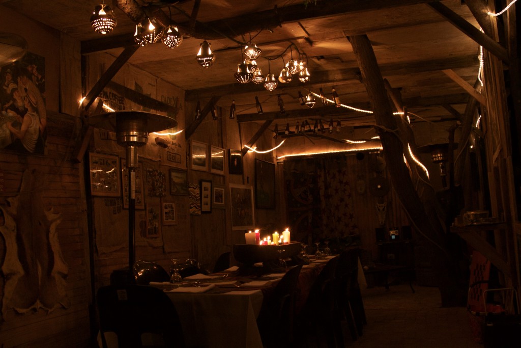
Just to remind you what Wamboland looks like, a few pics.

IMG_7039IMG_7045IMG_7046IMG_7048IMG_7053

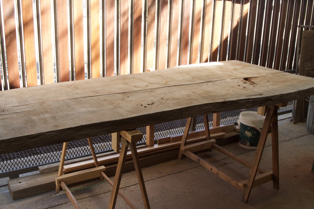
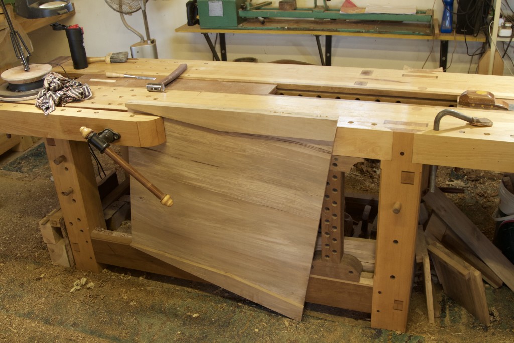
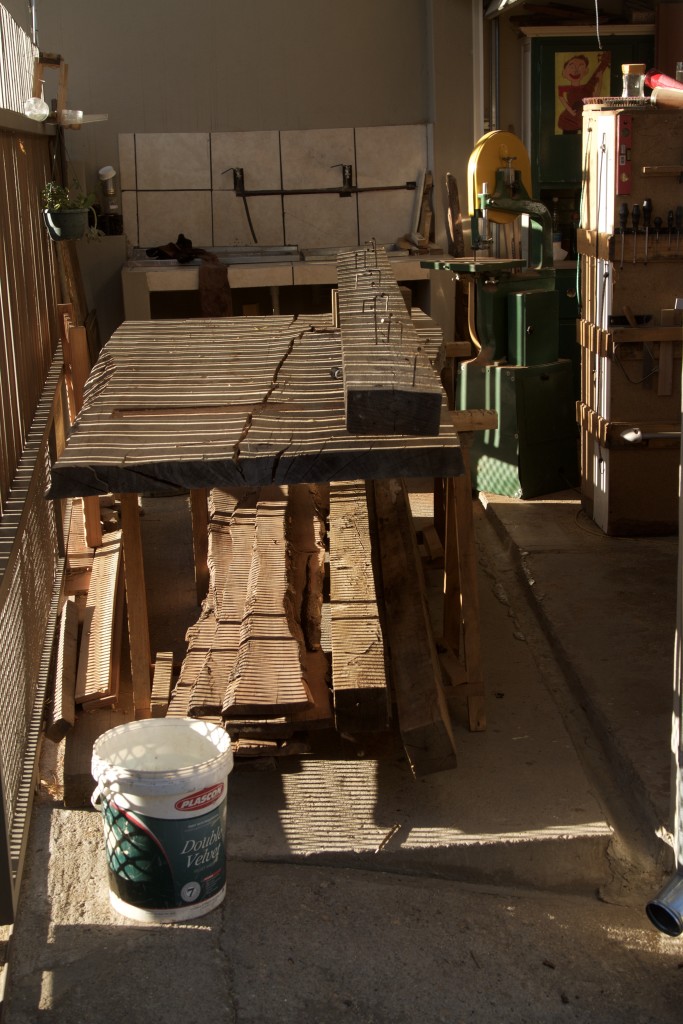
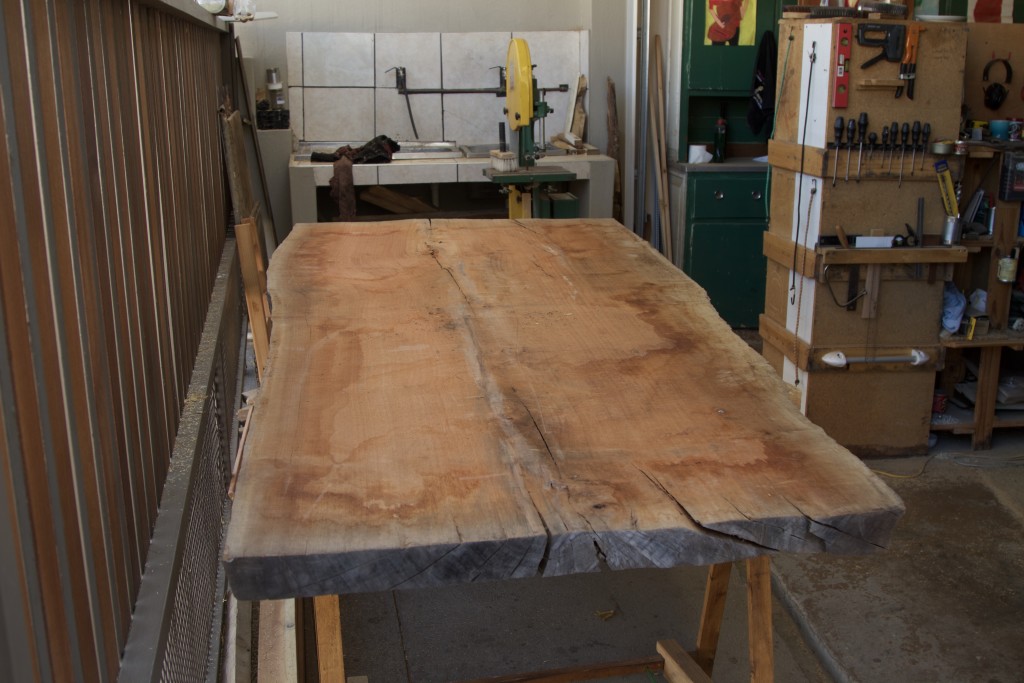
And here it is, a massive slice of Eucalyptus. Unfortunately I do not know much more about the origin and specific species of this wood. I know it came from South Africa and measures up to 2700 mm (length) x 1000 mm (wide at one end and 1200 at the other) x 70 mm (thick). After a bit of research on the net I would say it is probably what is called Rose Gum or Eucalyptus grandis, but by the time it is finished some of our Australian friends will probably give us a better idea of the exact species.

IMG_7265
I decided that this will be the underside.
IMG_7293
This will be the side facing upwards.

IMG_7266

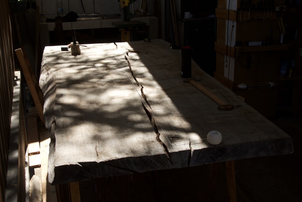
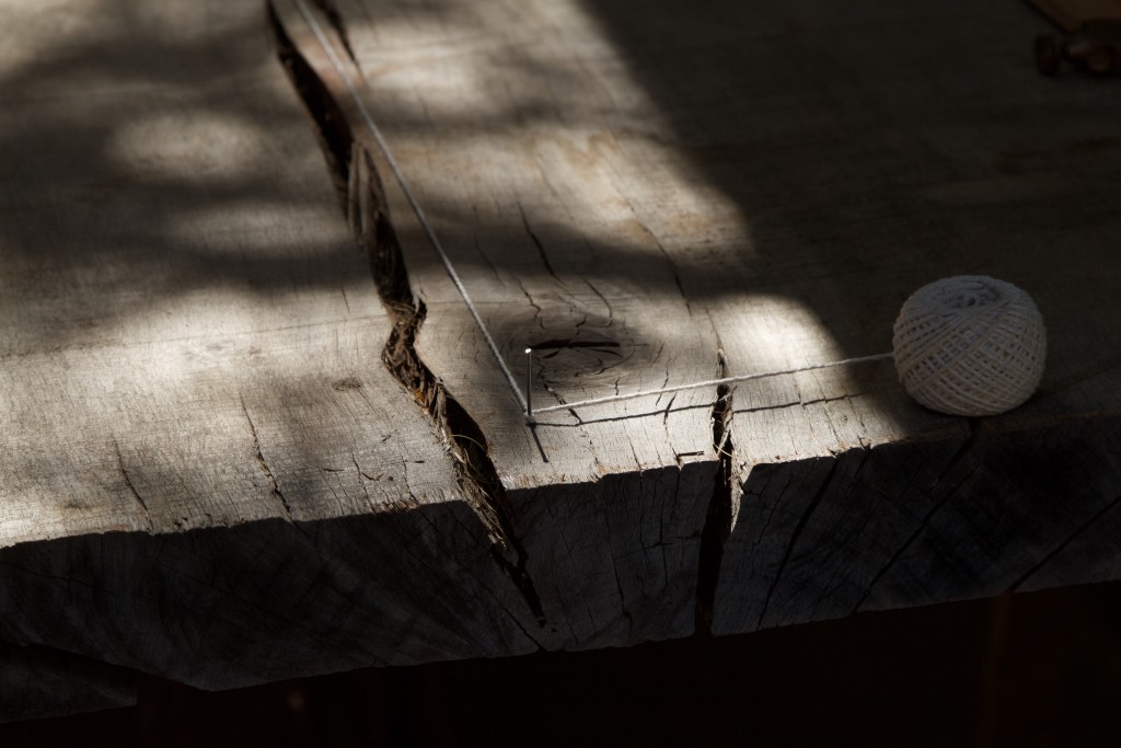
I apologise for the poor quality of this picture due to the contrast in lighting. What I am trying to illustrate is how I marked out the longitudinal centre line on the underside of the slab. Seeing that it is wider at one end than the other, I measured out the centre at each end and tapped in a panel pin. A piece of string stretched between the two pins then helped me to mark out the centre line.

IMG_7302IMG_7303

I used trammel points (not pictured) to divide the length of the slab into 5 equal parts along the centre line. The areas to be flattened for the legs were then marked out perpendicular to the centre line at the intersection between the 1st and 2nd fifth, as well as the 4th and 5th fifth. I hope that makes sense to native English speakers.

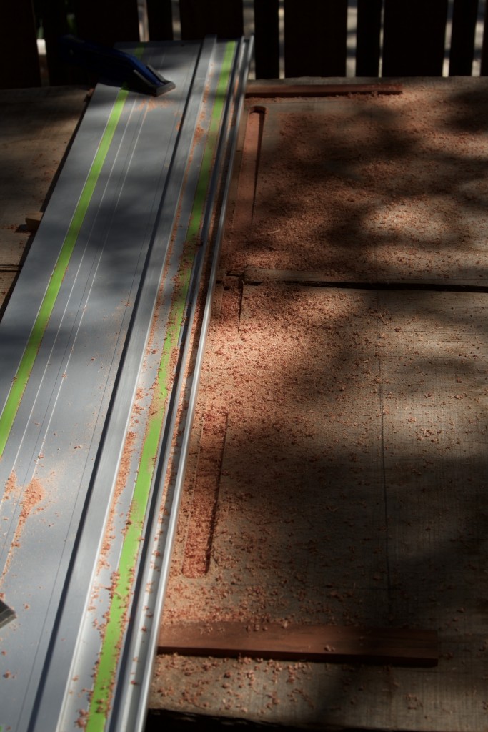
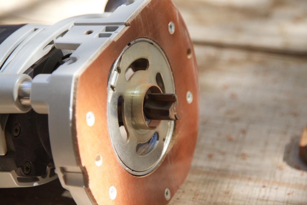
The first of these areas were flattened using my Festool router with the guide rail. I propped up the rail with bits of wood to stop it from bending. This was a very unpleasant experience. I have developed an allergy to electrical routers. They make too much noise and feel very unsafe to me.

IMG_7304IMG_7305IMG_7306IMG_7307IMG_7308

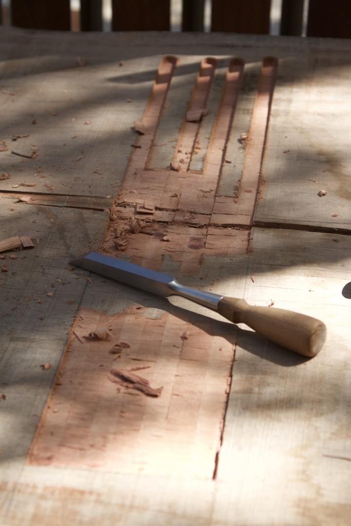
The waste was removed by chisel and a slick (not pictured).

IMG_7309IMG_7310

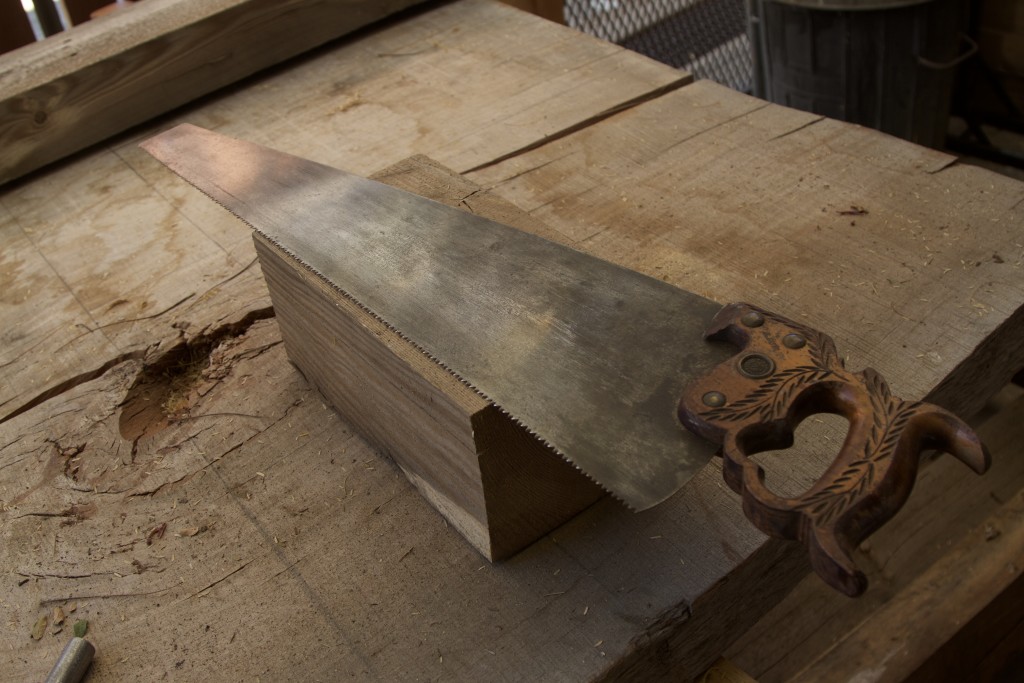
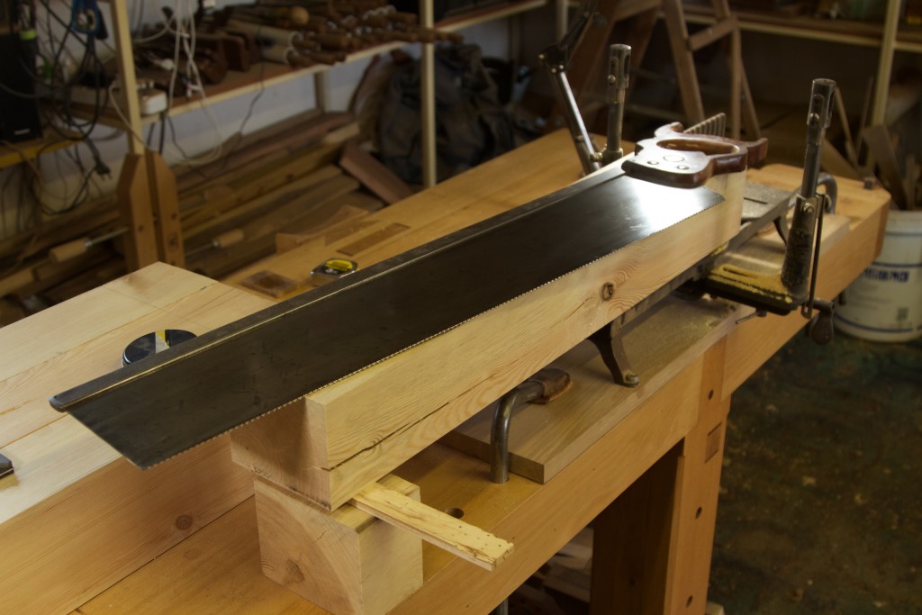
At this stage it was time to start the process of preparing the reclaimed Scots Pine, which will become the undercarriage of the table. I wrote a post on the origin of this wood which you can find here. These beams were first cut to length using my Disston no. 12 24″ crosscut handsaw and then ripped where necessary on the bandsaw. Unfortunately this was also the last job I will ever be able to do with this Chinese made 1982 model bandsaw, as it raised the white flag after an admirable career. Now I am in the market for a good affordable bandsaw, which is something that is probably impossible to find given the #Nenegate #Zuptamustfall #Nkandla #Failedtoupholdtheconstitution #Paybackthemoney #Khwesi #Itookashowerafterwards #eleventyseventyhundred #UntilJesuscomes-induced currency tragedy. RIP my dear friend, you have served us well (in reference to the bandsaw, not you know who).

IMG_7336IMG_7338IMG_7339IMG_7343

8/9/2016

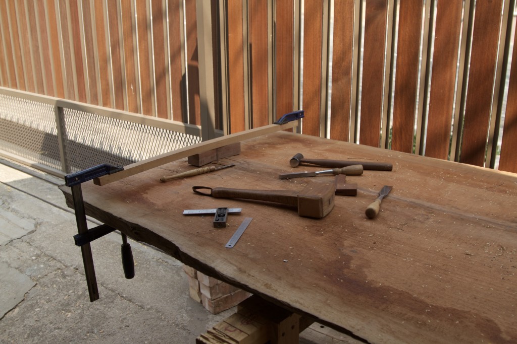
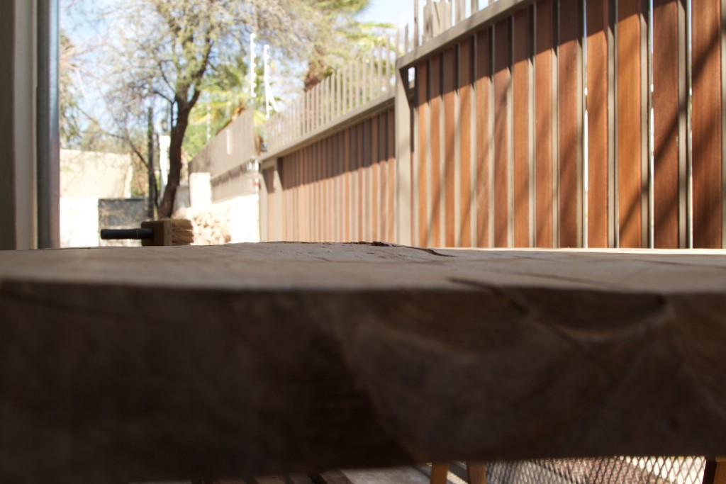
OK so back to the top. The second of the areas that needed flattening had quite a big bump in it. I decided to use my Festool tracksaw rather than the router.
IMG_7385
The bump should be quite obvious to see from this angle.

IMG_7383IMG_7384

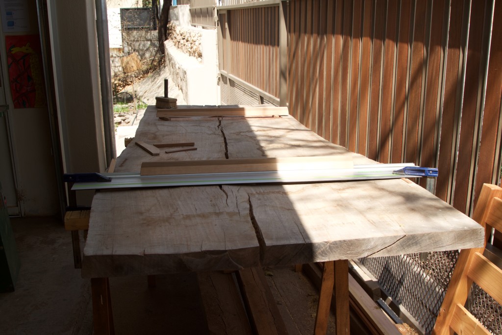
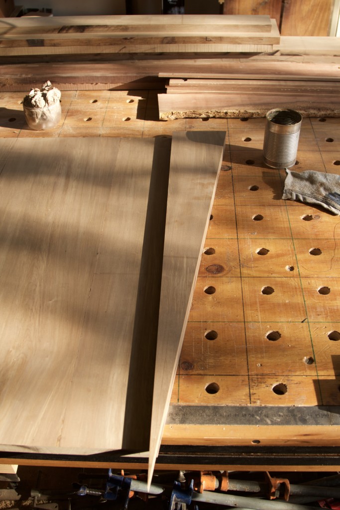
As you can see below, I again propped up the guide rail with bits of wood until the two winding sticks were lined up perfectly. This ensured that the two flattened areas would be in the same plane (or wind free if you like).

IMG_7386IMG_7387IMG_7388IMG_7389

So in this case I made a series of cuts checking the orientation of the guide rail with the aid of the winding sticks prior to each cut.

IMG_7390

I got lucky in that this area ended up “open” on one side, which allowed me to get in there with my shop made scrub plane to remove the waste (in conjunction with a slick and a chisel of course).

IMG_7391IMG_7392IMG_7393IMG_7394

This is the slick I mentioned earlier. The actual slick handle were removed for this job, so I simply seated an old pairing chisel handle as I did not feel up to turning a custom one for such a quick task. It is a Peck, Stow & Wilcox (PEXTO) for the sake of the tool geeks (like me).

IMG_7395IMG_7396

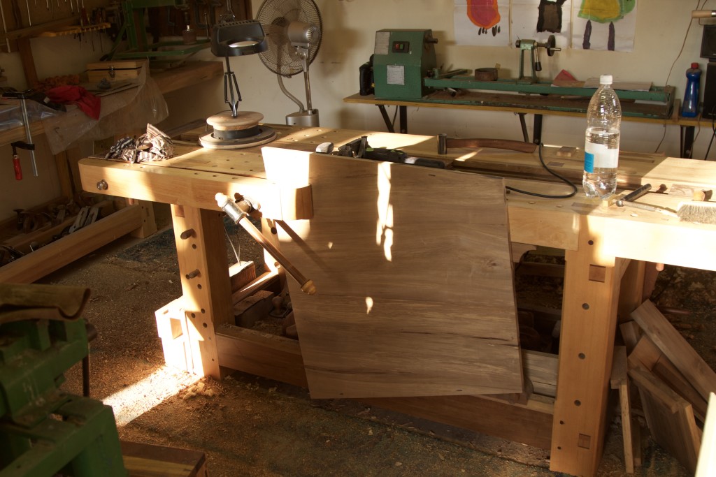
Seeing that there is a major crack in this slab of wood running all the way from one end to the other, I wanted to ensure that it does not fold like a book being closed when the top is handled during the building process. It actually feels quite resistant to such movement, but you never know. In order to lend it some extra support I screwed down these two heavy blocks of wood across the crack. I know, I know, possibly more screws than needed #JonathanWhite!! This is of course only a temporary arrangement, while working on the top. Eventually the undercarriage will fulfil this role.

IMG_7397IMG_7398IMG_7399IMG_7400IMG_7401IMG_7402

Here you can see the legs, (some of the) stretchers and aprons after hand and machine planing.

IMG_7370

The legs being cut to final length.

IMG_7373IMG_7374IMG_7375

Hand sawing of joinery.

IMG_7377IMG_7378IMG_7379IMG_7380IMG_7381IMG_7382

12/9/2016

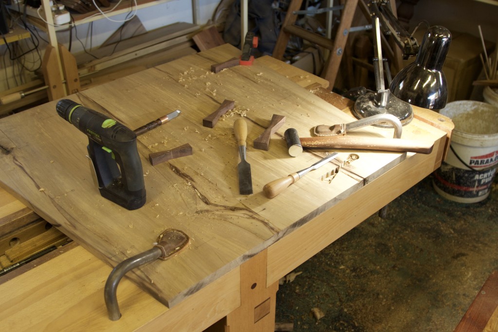
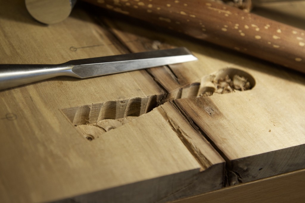
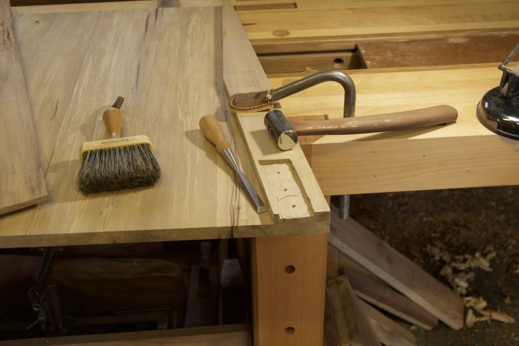
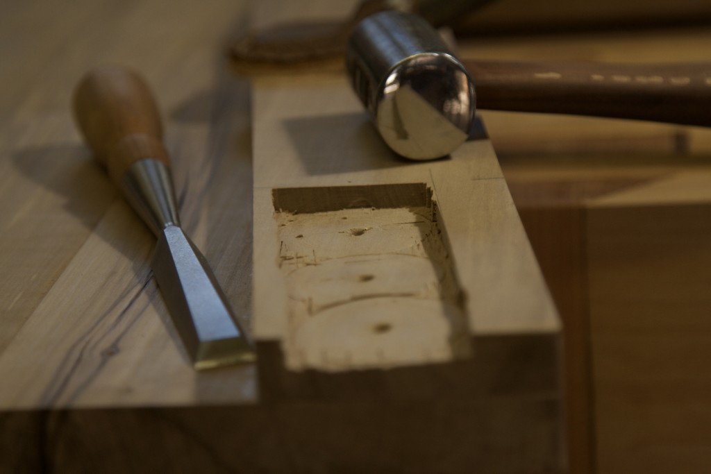
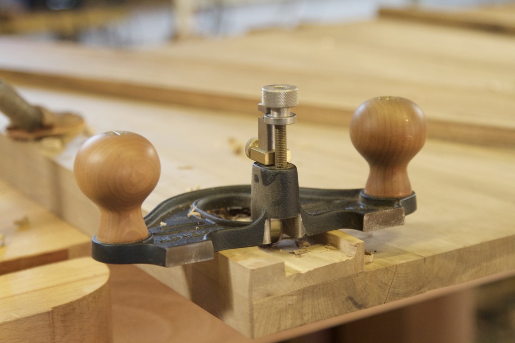
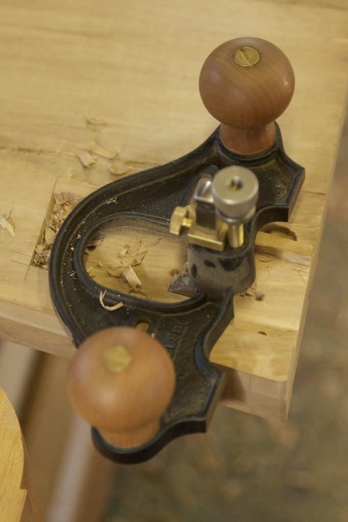
The pictures illustrate a technique that I employee fairly often now. I leave an area of waste which helps to stabilise the sole of my Lie-Nielsen router plane. Once the router plane have the area perfectly flat and to it’s exact depth I remove the waste and use the flat area created by the router plane as a reference surface for a pairing chisel.

img_7426img_7427img_7428img_7429

For some reason I did not take a picture of the part with the waste removed. Sorry.

img_7430

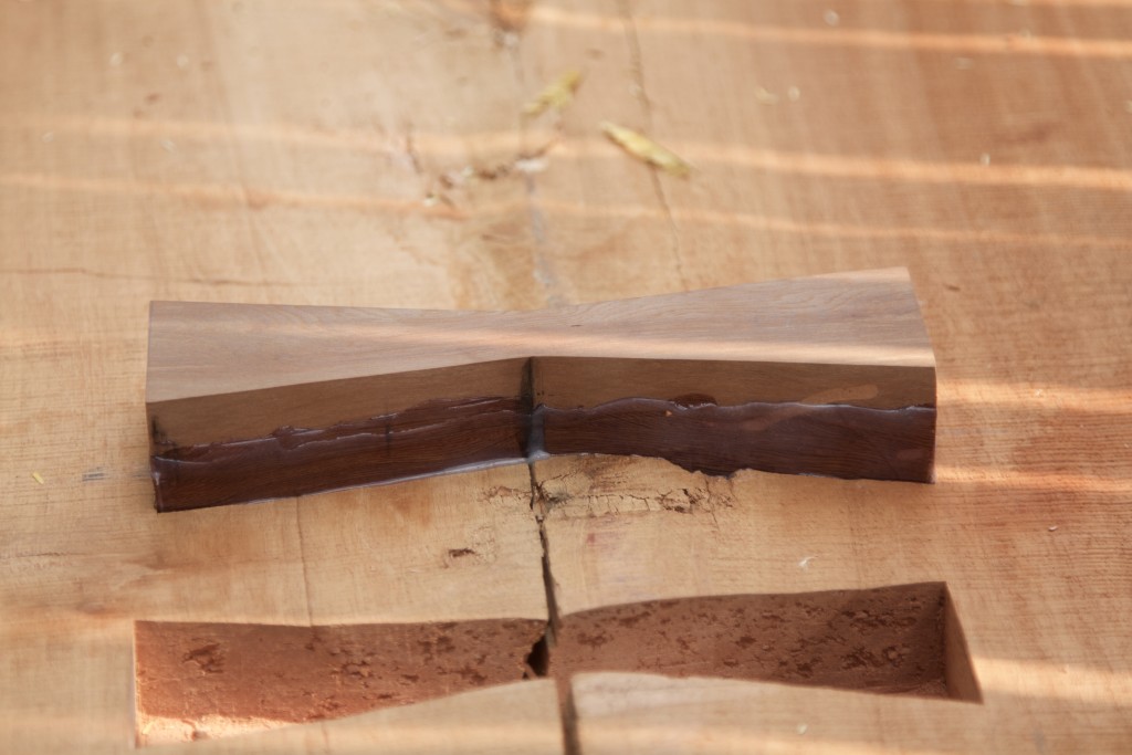
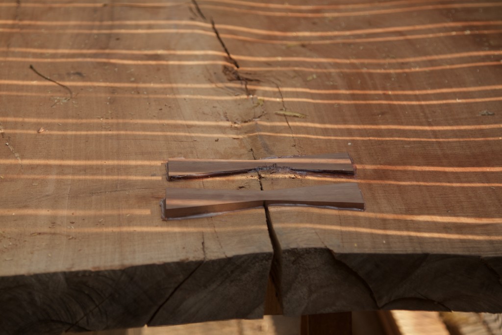
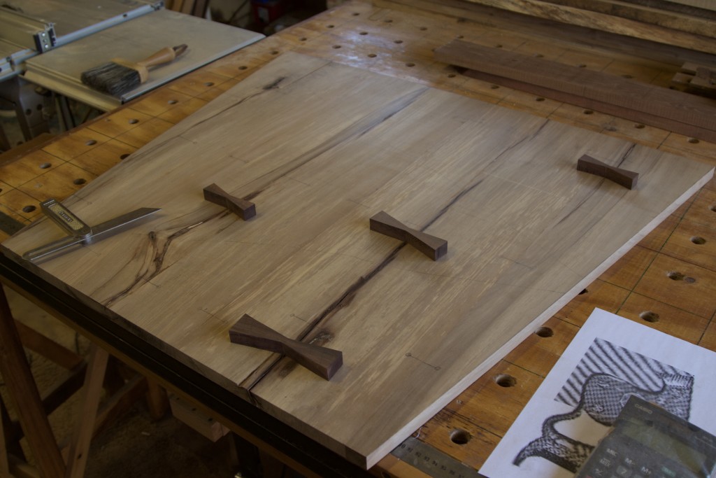
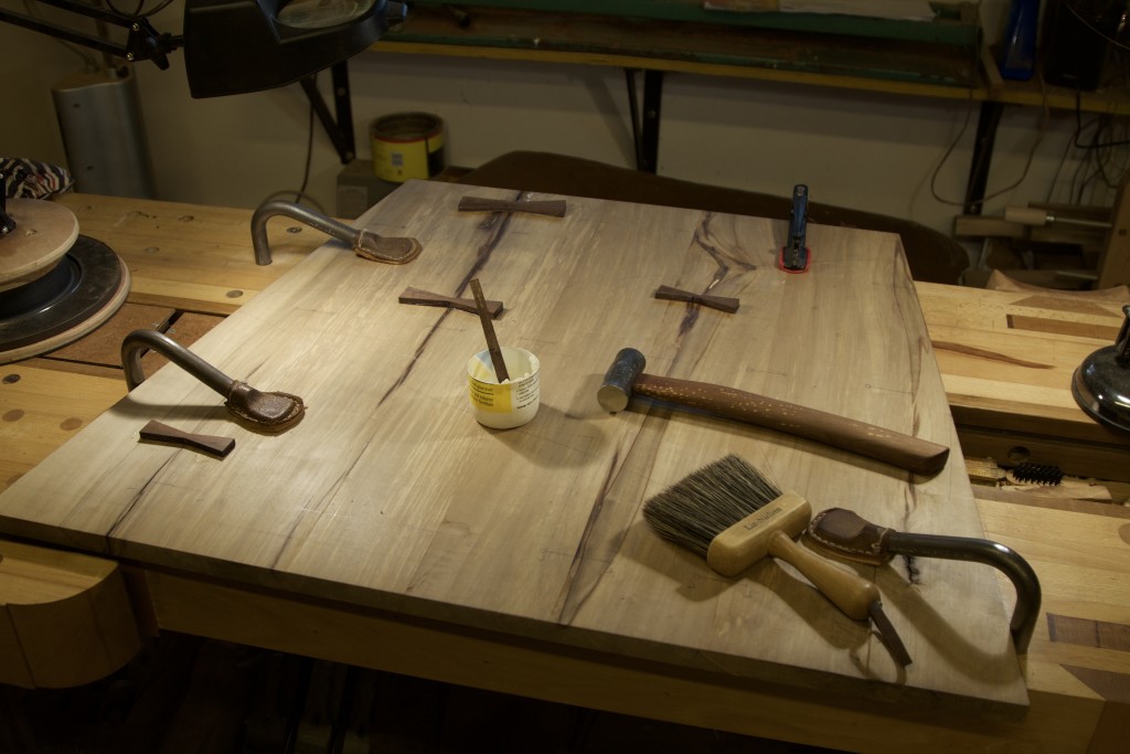
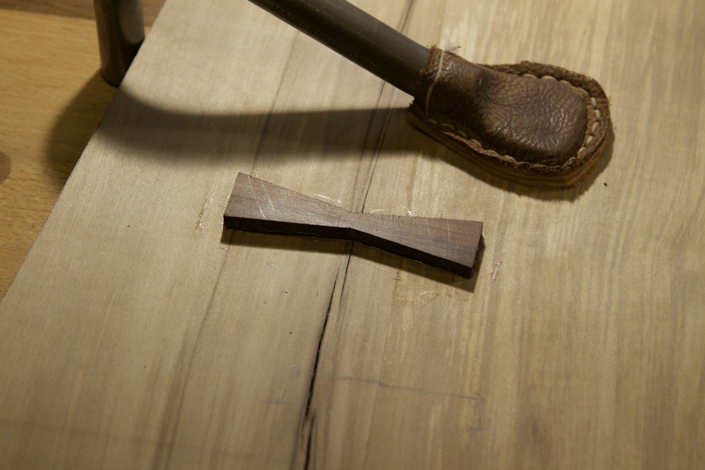
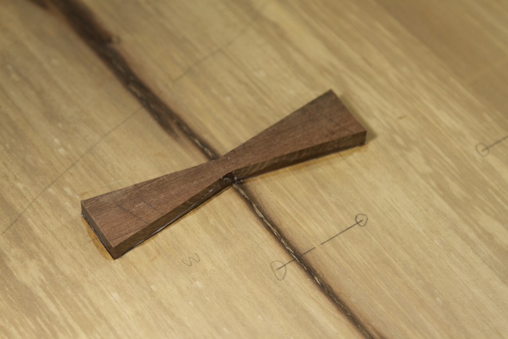
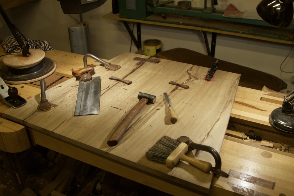
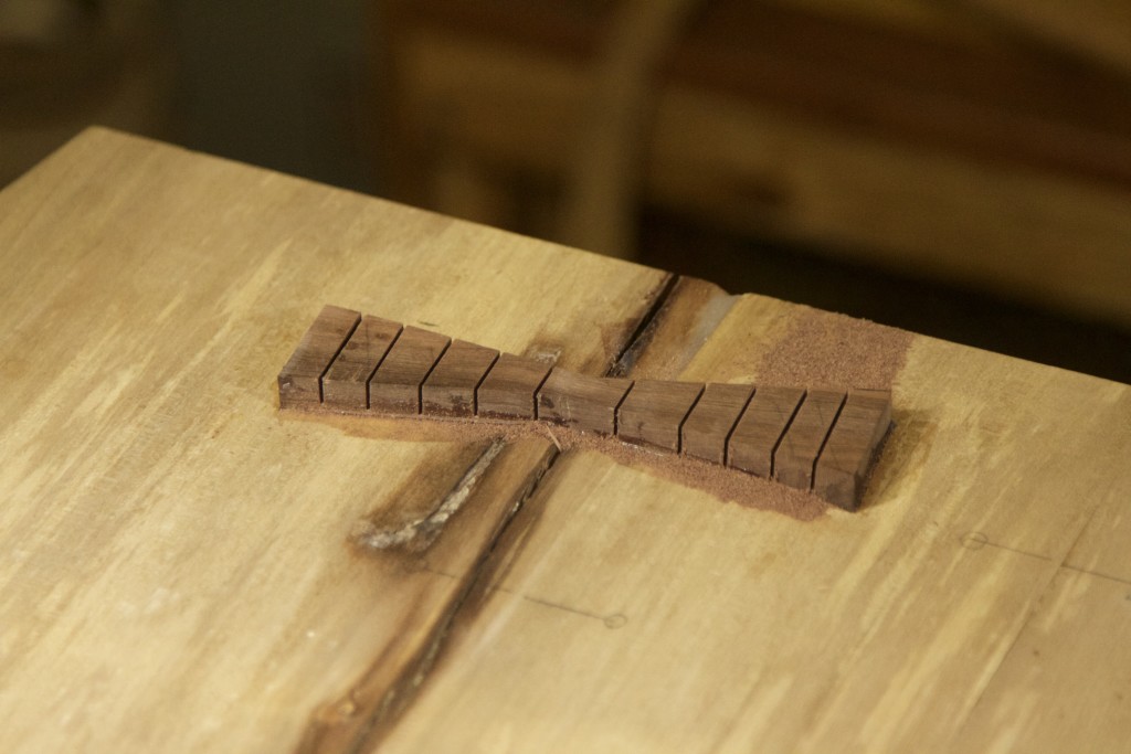
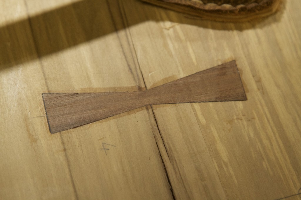
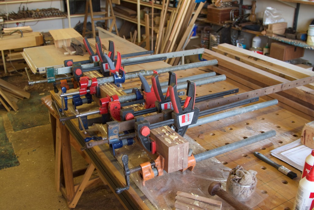
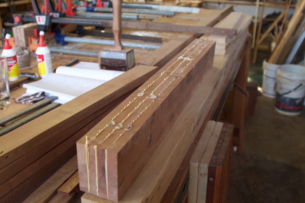
The next major task is to stabilise that massive split in the top Nakashima-style as approached from the side that will face upwards. For this purpose I had to laminate Kershout stock to created massive Dutchmen (aka doveltail keys).

IMG_7371IMG_7372img_7412img_7413img_7414img_7418img_7419

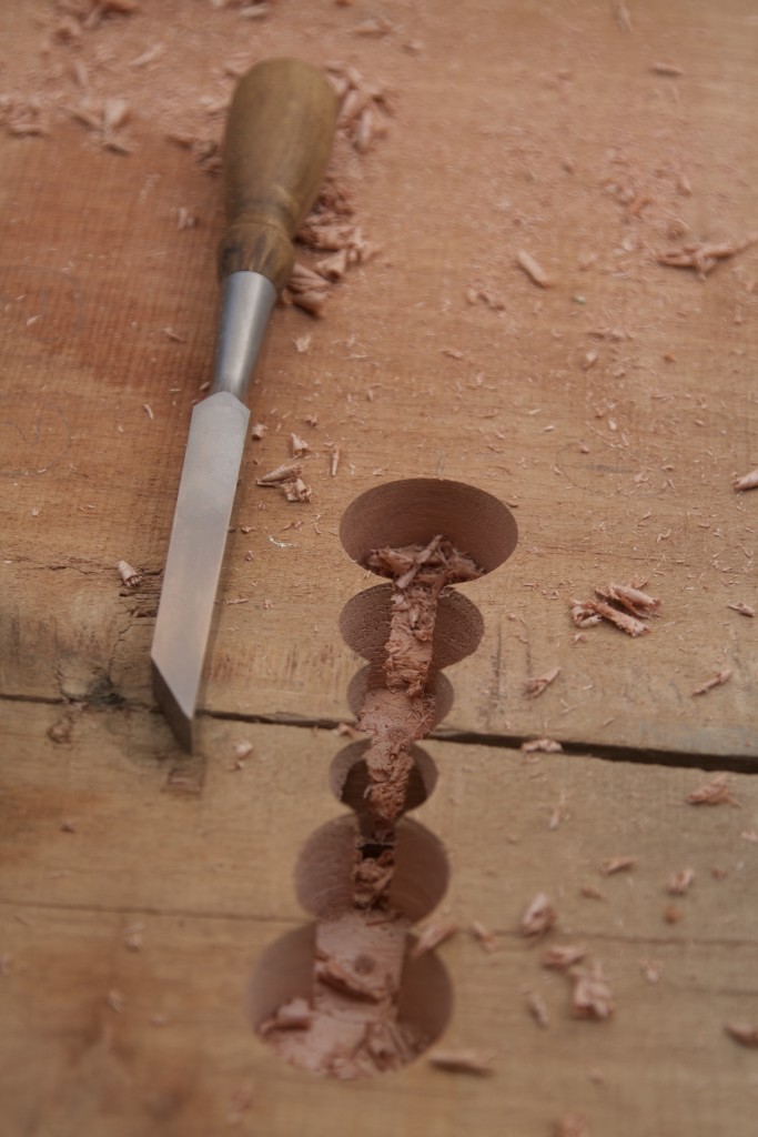
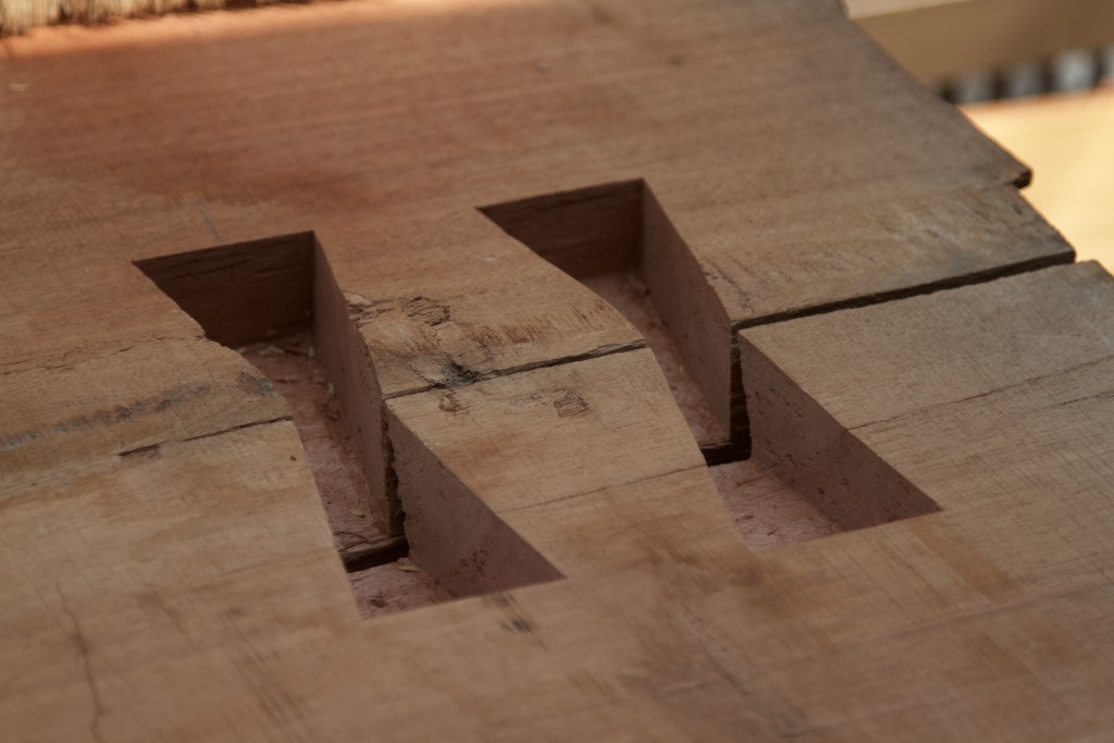
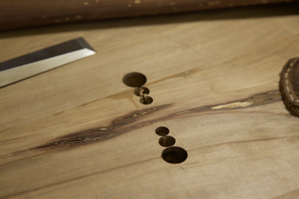
Now they need a cosy new home. As I have described this process previously I will not bore you with it again. The pictures will probably do the job anyway.

img_7420img_7422img_7423img_7424img_7425img_7433img_7434img_7435img_7436

Glued into position using slow setting epoxy.

img_7437img_7438img_7439img_7440

At this stage I am in a race against time as this top is living outside my shop (due to it’s size) so I need to finish my Dutchmen-placement-activities before the rain comes. If we are lucky we might see a few drops around the start of October. The top needs to be safe and sound under roof in Wamboland by then. Then I can happy toil away at the undercarriage (which does fit in the shop) until it is ready to be joined in matrimony.
My Second commission – part 6

9/8/2016

It has been a long time since I posted the previous update on this project, so here goes.

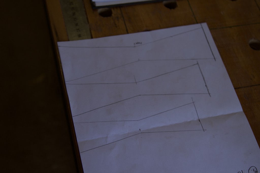
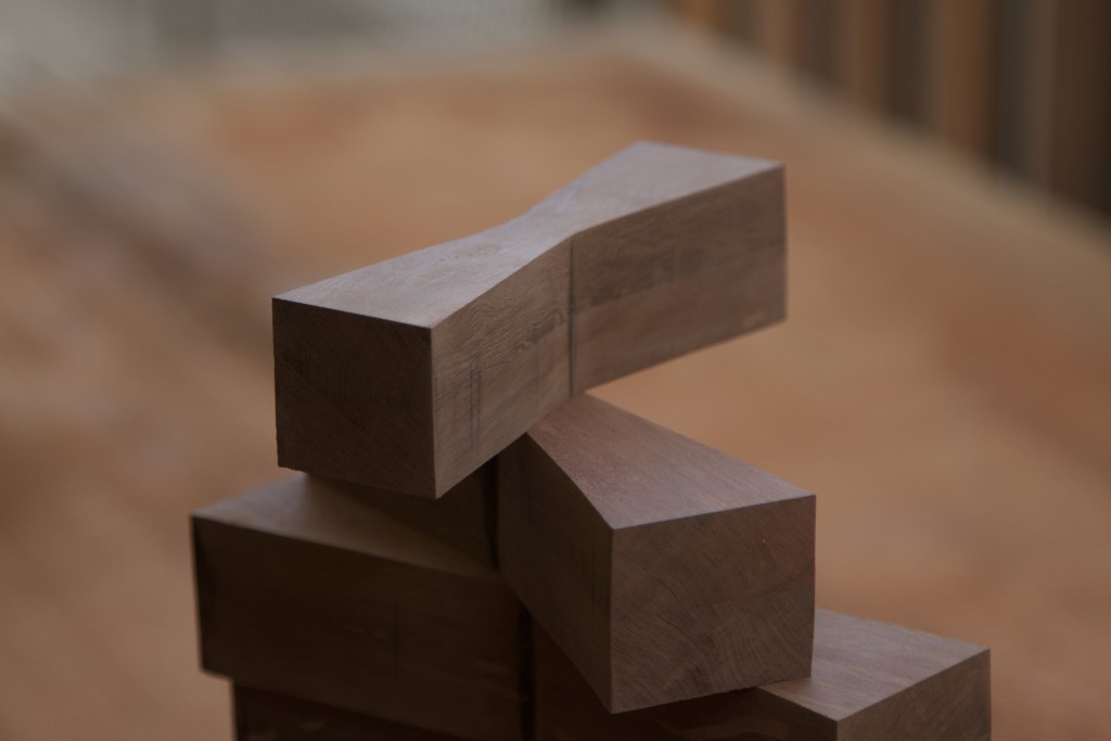
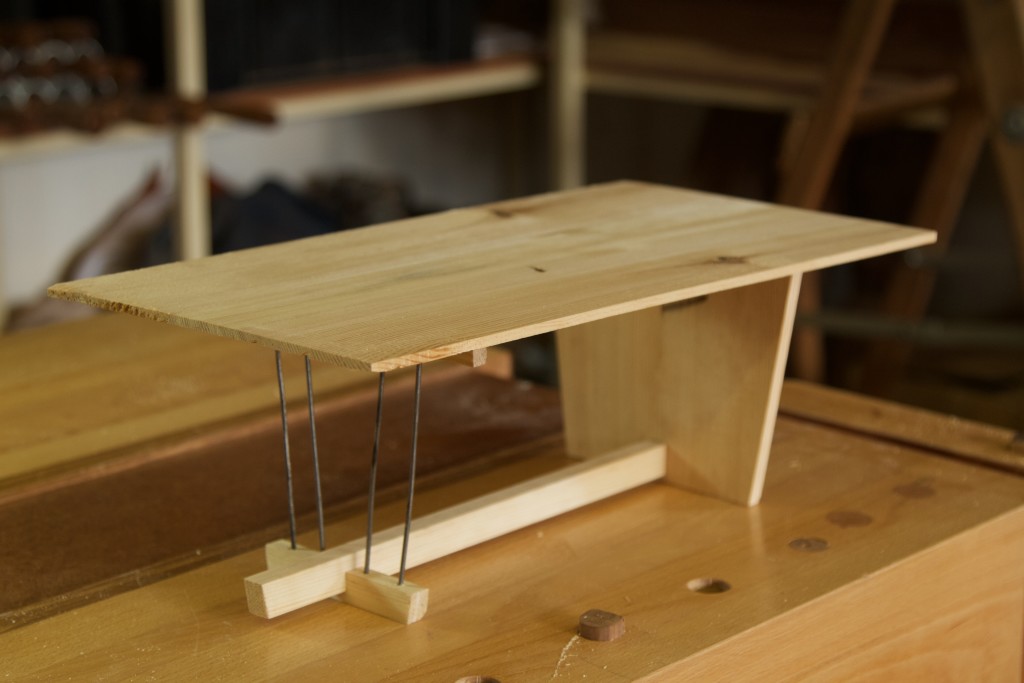
Maybe we should first just remind each other what we are aiming for. Below are two photos of the final version of my protracted design process in the form of a small mockup. In this post you will see how I progress with work on the solid trapezoid shaped leg and stock preparation/lamination of the various parts of the so called Windsor leg.

IMG_6281IMG_6279

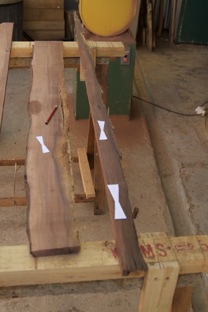
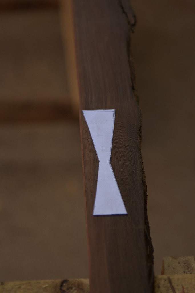
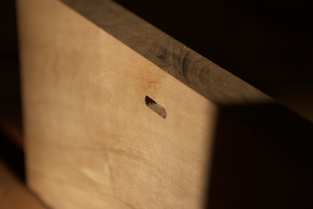
In the pictures below you can see how I cut dovetail keys from Kershout. I recently learned that the these keys which were made famous by George Nakashima are also known as “Dutchmen”. Why, I do not know, maybe Dutchmen like wearing bowties??

IMG_7253IMG_7254

The keys placed on the face side of the trapezoid leg.

IMG_7256IMG_7257

The Dutchmen is meant to stabilise natural cracks in the wood. Of course it also adds a certain je ne sais quoi, as you would expect.

IMG_7258IMG_7259IMG_7260IMG_7261IMG_7262IMG_7263IMG_7264

I used slow setting epoxy to fix the Dutchmen about two thirds of the way into the thickness of the Witpeer panel. As you can see they stood proud of the surface of the panel by quite some margin (post insertion).

IMG_7271IMG_7272IMG_7273IMG_7274IMG_7275

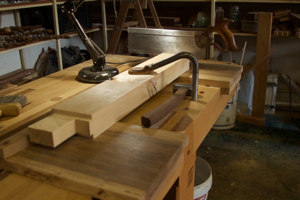
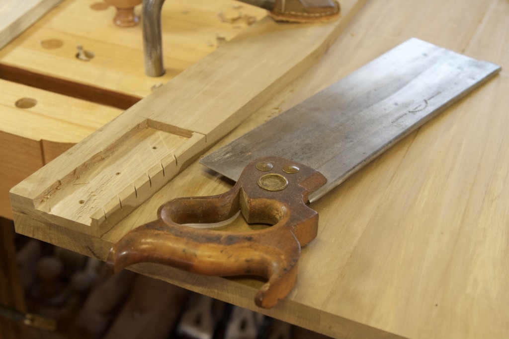
As a result of how incredibly hard the Kershout is and the amount of material to remove I followed the approach pictured. Several crossgrain cuts with a carcass saw, followed by chisel, followed by Jack plane.

IMG_7276IMG_7283IMG_7277

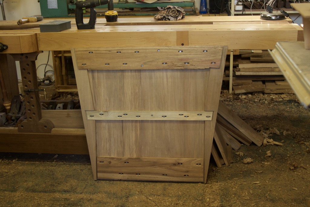
The two edges of the panel were then laminated with the off-cut piece of Witpeer flipped over head-to-toe and back-to-front. This ensures the best colour match possible and per definition results in the grain running perfectly in the same direction. The lamination on the one hand aims to create a component that is twice as thick as the top of this table, which is a choice made in the interest of pleasing proportions (from a design perspective). It also creates space to hide a second layer of strips that run perpendicular to that of the first layer. This is quite useful when working with my beloved feral hardwood as it has a tendency to warp in the absence of something to keep it honest.

IMG_7285IMG_7284

As you can see below, I used Dominos to keep the edges flush during glue-up.

IMG_7286IMG_7287IMG_7289IMG_7290IMG_7292

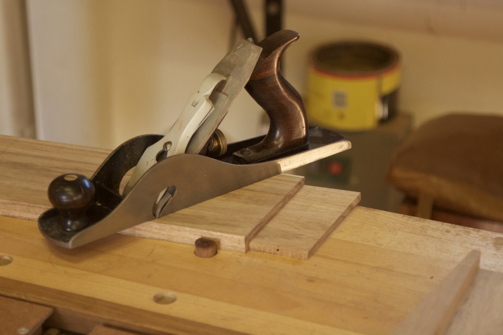
After glue-up the edges were cleaned up with a hand plane.

IMG_7295IMG_7298

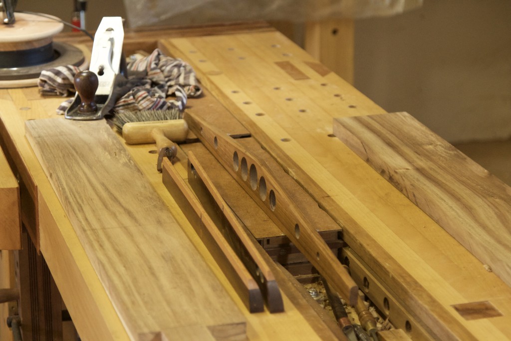
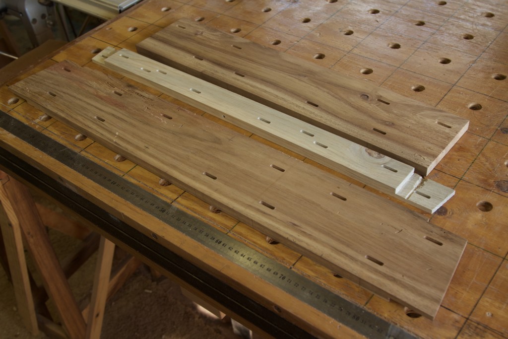
Next came the preparation of the strips of wood that will run perpendicular to the grain of the trapezoid panel. This involved the usual array of tools including winding sticks, straight edge, and hand plane.

IMG_7267IMG_7269

As this will ultimately be a layer that will be completely hidden from sight, I used proper off-cut level stock.

IMG_7268

Preparing lapjoints  at end of the perpendicular strips.

IMG_7299IMG_7301

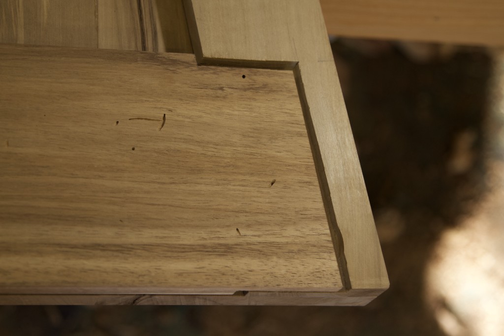
Followed by the mating lap joints in the raised section of the trapezoid panel.

IMG_7311IMG_7317IMG_7318

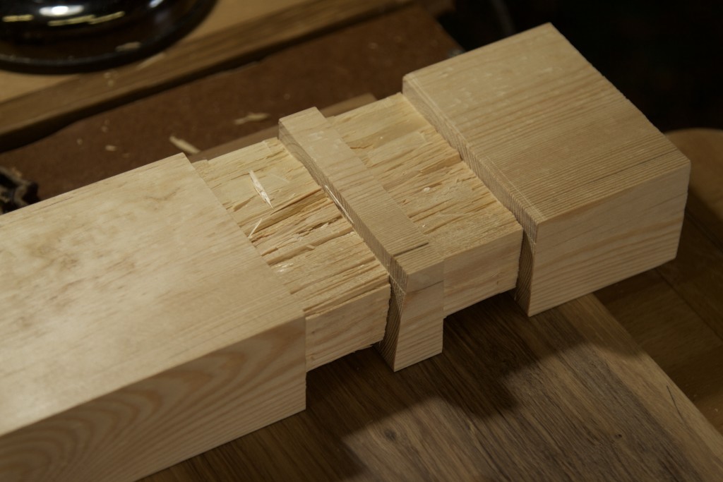
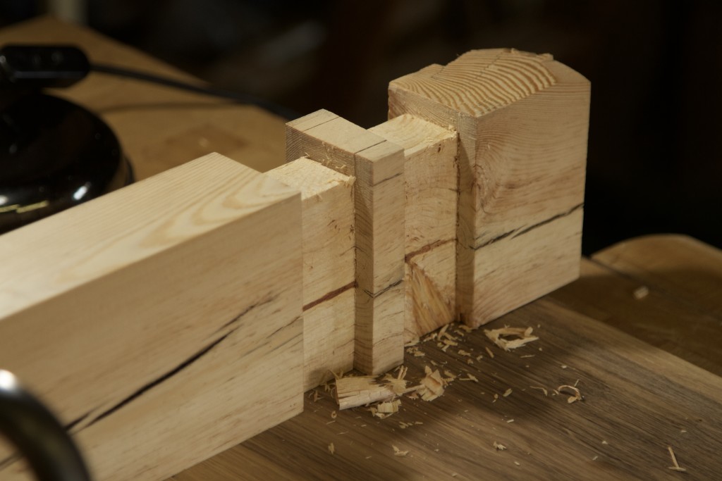
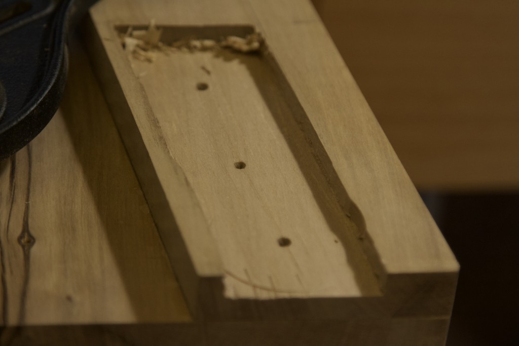
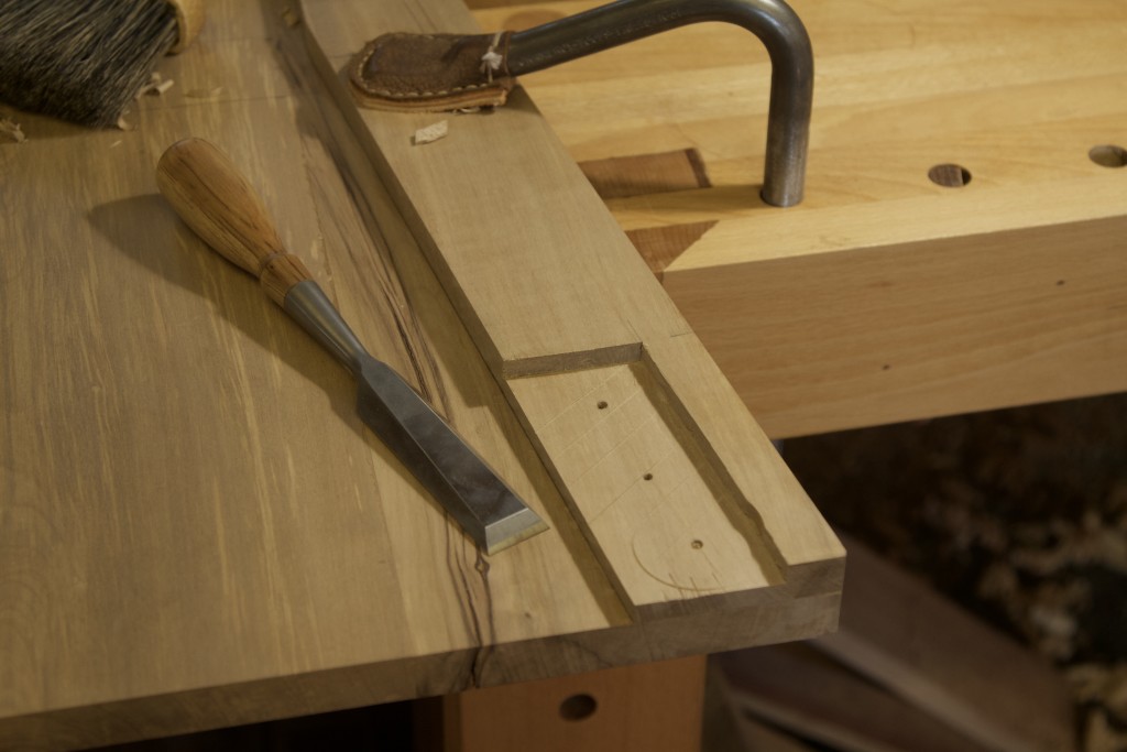
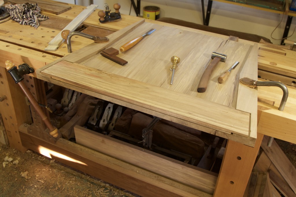
A useful trick that I employed here is to leave a narrow strip of waste intact to support the sole of the router plane while shaving 90% the floor of the lap mortise (for lack of a better term) perfectly flat and to the desired depth. Then it is easy to use the flat area as a reference surface for your chisel while pairing away the remaining waste.

IMG_7320IMG_7321IMG_7322IMG_7324IMG_7325IMG_7326IMG_7327IMG_7328IMG_7332IMG_7331

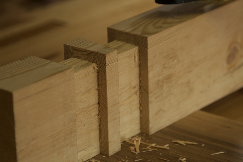
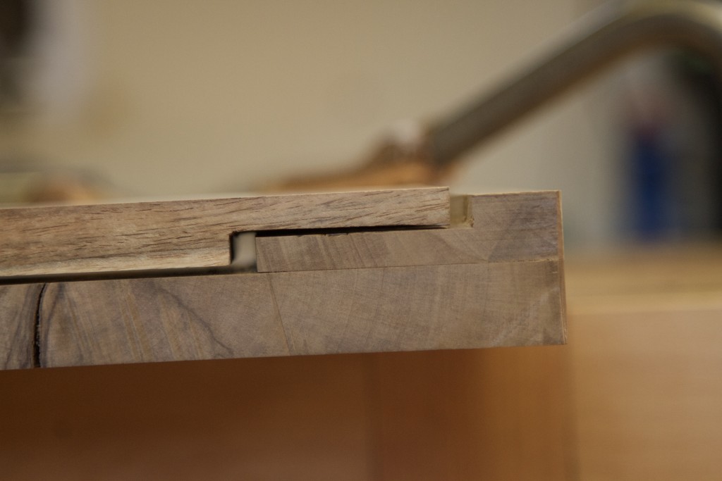
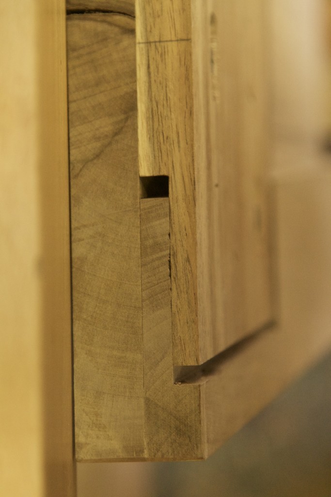
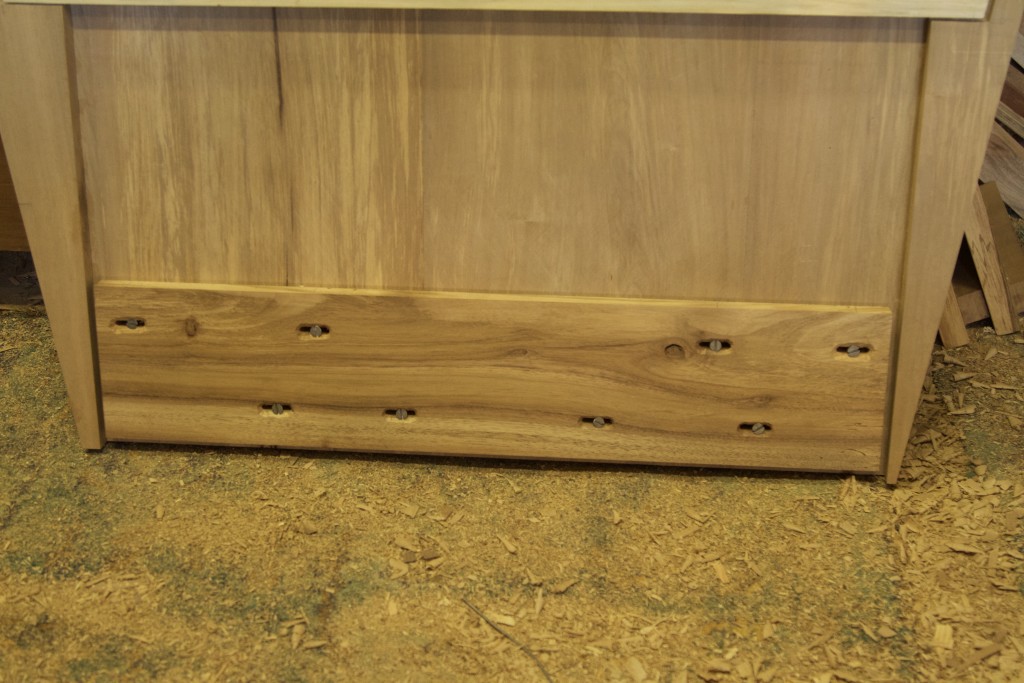
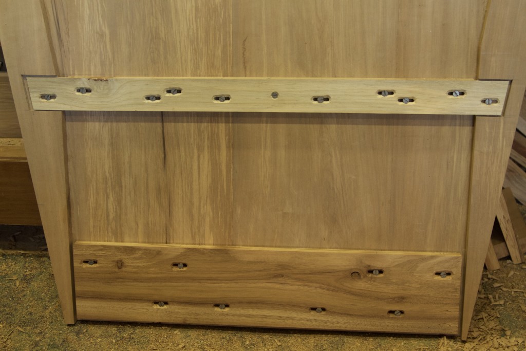
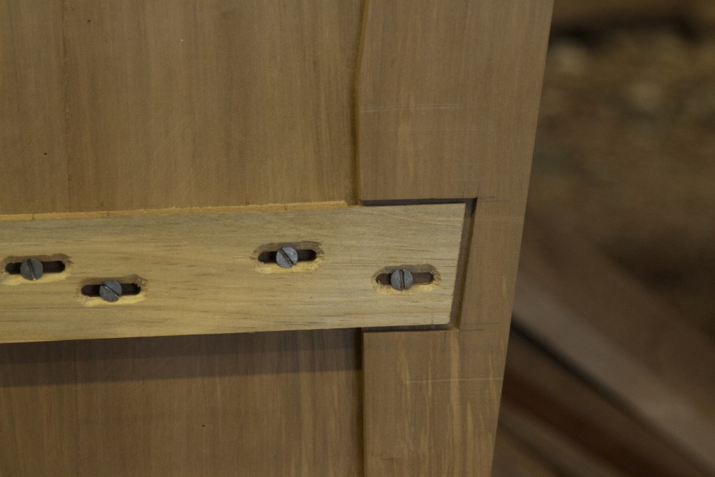
The gaps you see in the lap joints are there to allow for ample movement of the trapezoid panel with changes in ambient humidity, while the perpendicular strips resist warping. You will also note the slots around each screw which allows for the same thing. I used my Festool Domino to cut the slots. At this stage the leg is ready for it’s final layer, which will cover up the perpendicular one and take the thickness up to 44 mm. More about that in a month or so as we now have to first build the other leg using Windsor technology!!! It will be my first time so I am stressing!!!

IMG_7329
This picture was take before the joint was fitted perfectly, but does show the gaps left to allow movement.
IMG_7348
Here you can see the lap joint after proper fitting.

IMG_7330IMG_7335IMG_7344IMG_7345IMG_7346IMG_7347

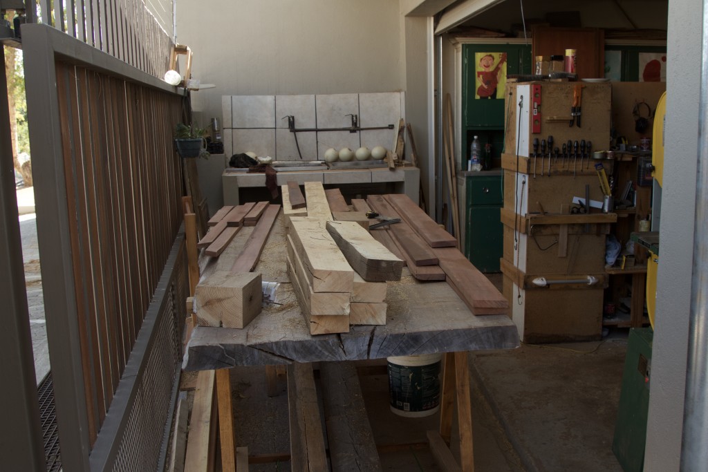
At the level of the paint bucket you can see the Kershout I chose for the Windsor leg.

IMG_7337

6/9/2016

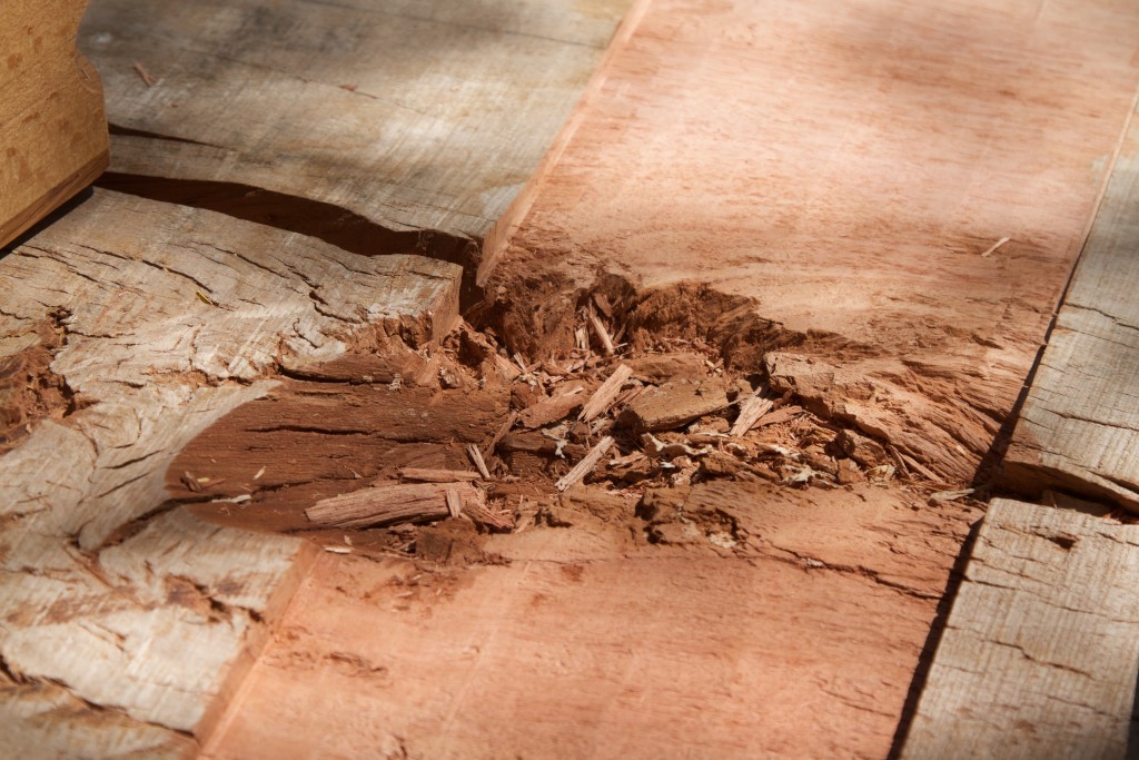
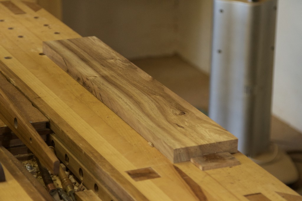
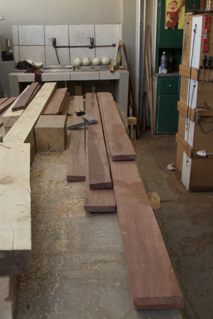
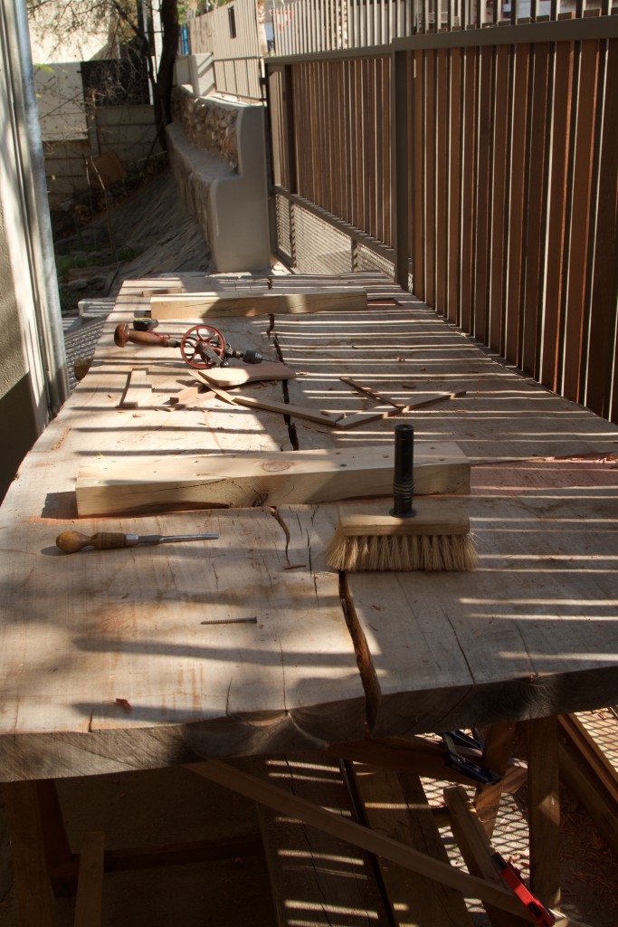
I can assure you that the time and effort it takes to liberate the few pieces of Kershout (aka Candle Wood or Pterocelastrus tricuspidatus)  pictured below from the pile pictured above will surprise you. This stuff is very hard and extremely heavy. It actually sinks in water!!! The Kershout is the deep red coloured wood.
IMG_7351
I am sure it is quite obvious from this picture that even after liberation and some planing these pieces still look as wild as a pet rhino.

IMG_7349IMG_7350

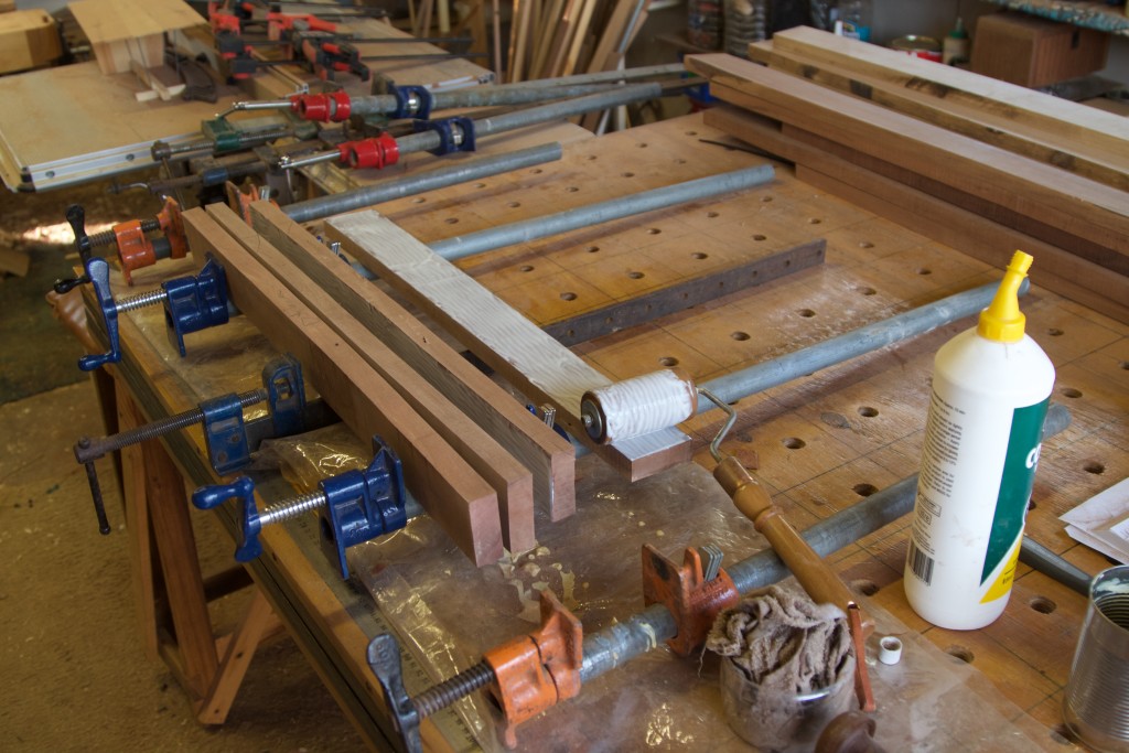
Below I am laminating the top and bottom beam of the Windsor leg.

IMG_7366IMG_7367IMG_7369

In the next addition of this series of posts we will plunge into the world of Windsor technology.


Coconut shell lights

20/6/2016

I would like to apologise sincerely for my long absence from the blogosphere. We lost our internet connection at home for several weeks which curtailed my ability to load photos to this website. I also missed out on shop time for over a month due to traveling and other challenges. At the moment though, I am back in action working on several exciting projects.
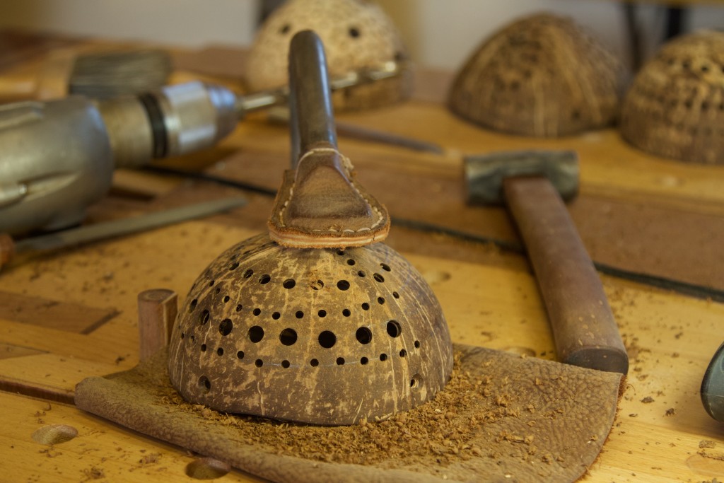
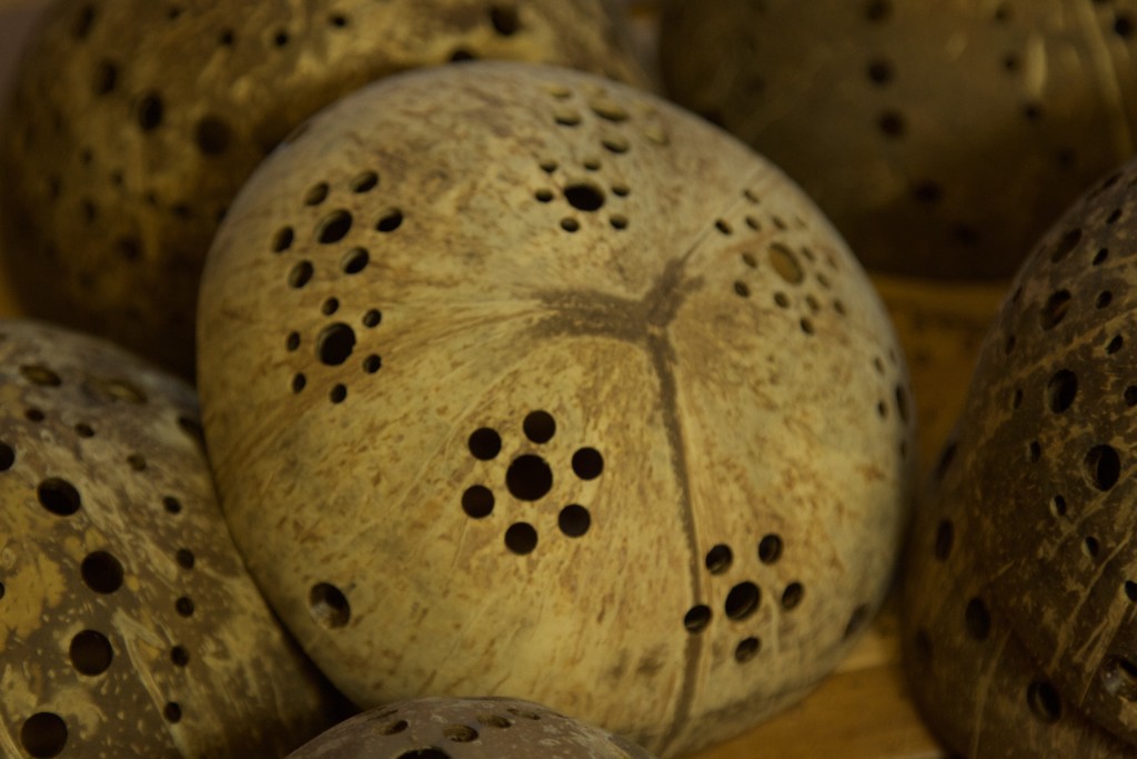
As you might remember from a previous post, we had a wonderful week in Thailand some months ago. We picked up a whole heap of coconut shells in Ying’s (our cooking class teacher) backyard. They were then smuggled in our luggage via Hong Kong back to Namibia. A few of them were damaged during the arduous trip, which I then turned into spoons. The rest were lined up to become lights.

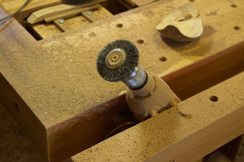
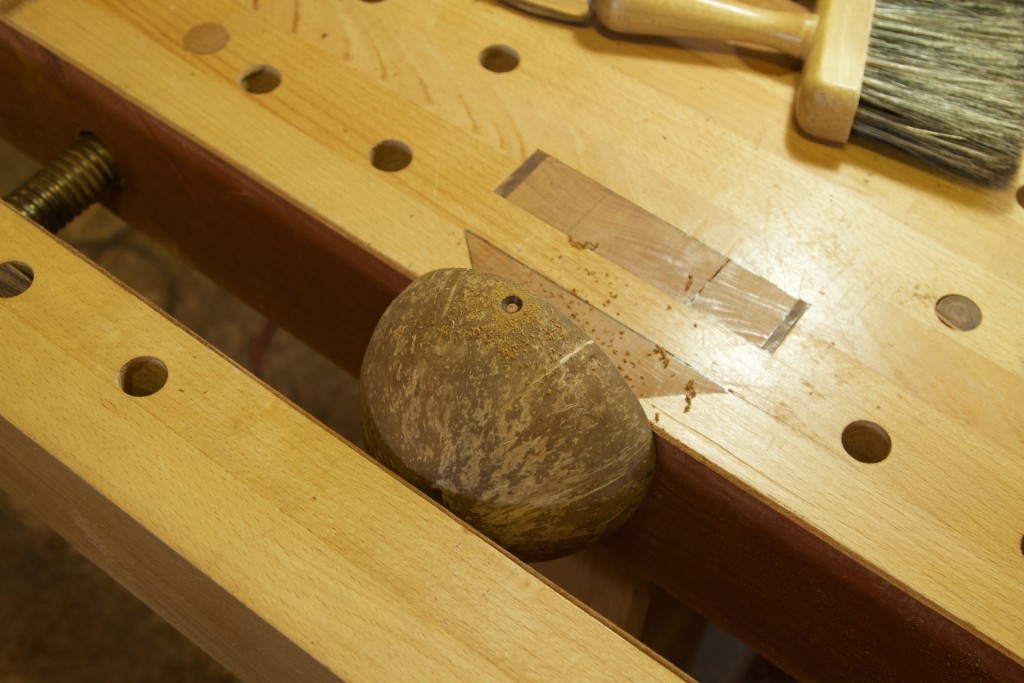
It is quite a mission to get rid of the fibrous material on both the in and outside of the hard shells. I used the wire bits pictured to do just that.

IMG_6938IMG_6929IMG_6999IMG_6996IMG_6997IMG_7000IMG_7001

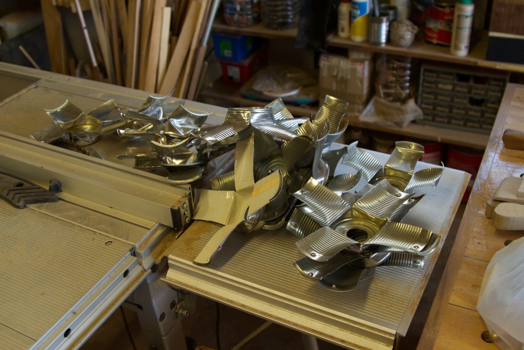
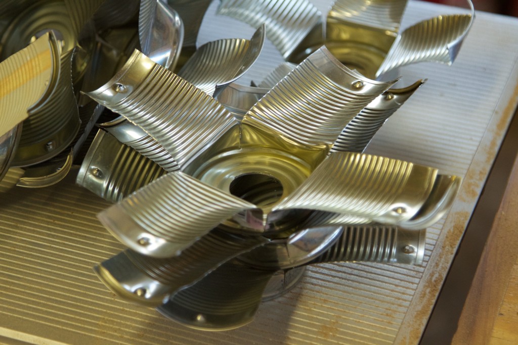
For the other halve of the light I used empty tin cans from household use. The big hole is for the light fitting.

IMG_7002

The cans were then snipped into four strips to allow it to flare open.

IMG_7010IMG_7011

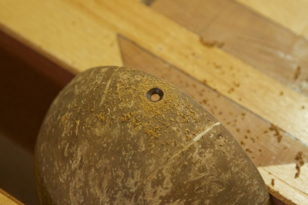
Each of the four strips are attached to the edge of the coconut shells with one self-tapping screw.

IMG_7004IMG_7005

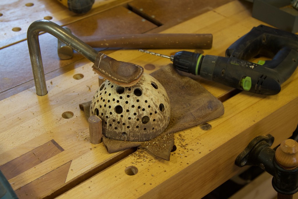
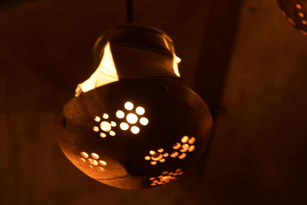
In order to allow light to shine through the shells I drilled sets of “carefully messed up” holes. The inspiration for this is Aboriginal art from Western Australia that I saw many moons ago while at a Congress in Perth. As I am sure you can imagine, this took ages to accomplish.

IMG_7012IMG_7013IMG_7015IMG_7016IMG_7017IMG_7018IMG_7019IMG_7022IMG_7023

One coat of Woodoc enhanced the beautiful natural colours of the shells.

IMG_7033

I decided not to include any photos of how the lights were wired up as it might become a legal liability for this website, not to mention the myocardial risk in might impose on people like Jonathan White. So here they are hanging off the roof of our Shebeen called “Wamboland”  located in the backyard.

IMG_7044IMG_7046IMG_7045IMG_7404IMG_7406IMG_7407

An accidental arty photo.

IMG_7403

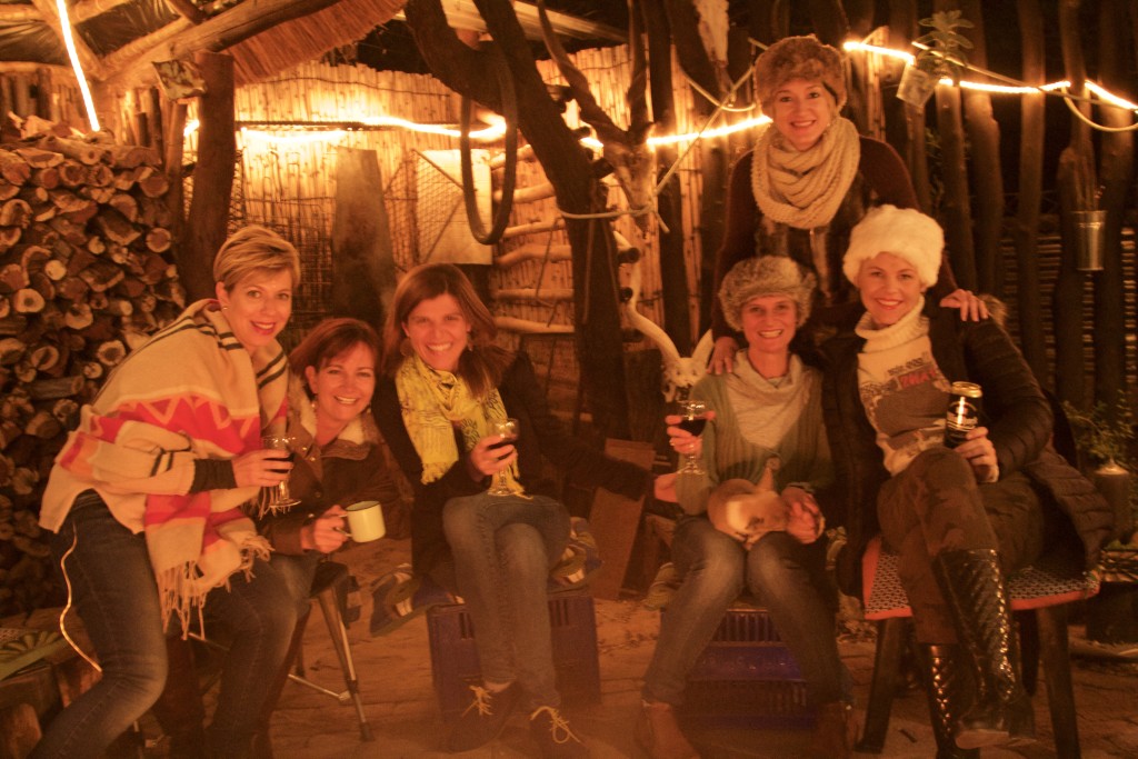
As an added bonus I include a few picks of super hot Namibian chicks hanging out at the Shebeen a while ago. If some of the photos are less than perfect it is because they were not able to keep still for long enough given the slow shutter speed in such a low light setting. Certainly not as a result of anything to do with the photographer!!

IMG_7039IMG_7053IMG_7054