The year is hurrying towards it’s inevitable end and the temperatures in my tropical haven are racing upwards at the same rate. The massive shift in ambient humidity that a good rainy season can induce always wind me up to get joinery that is supposed to last a really long time assembled during the driest part of the year. In my case that means before the end-of-year holidays, as the proper electric storm driven downpours tend to ignite a sudden hike in humidity around mid January. That is of course if we are lucky, because water has been in short supply in this sweltering savanna of ours.
For the purpose of this project I wanted to get the two leg-assemblies done before we leave for a hitherto tranquil spot on the Azanian south coast. Unfortunately the Zuptopian conglomerate has since done it’s utmost to “poison and destroy my brothers”, but let’s not dwell on the bane of my life while we could be discussing woodwork.
As discussed before, I prefer using Assegaai for my custom made drawbore pegs. I usually try and find a perfectly straight-grained piece before ripping strips on the table saw that are then fed to my Stanley no. 77 dowel making machine (not pictured). Unfortunately it is pretty much impossible to split (as apposed to rip) stock along the grain then using the no. 77 as you need perfectly square strips, but if you use fairly straight stuff it still turns out dowels that are far superior to the rubbish bought in local stores. I wrote in more detail on this process in previous posts.
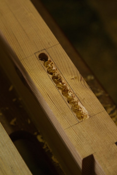
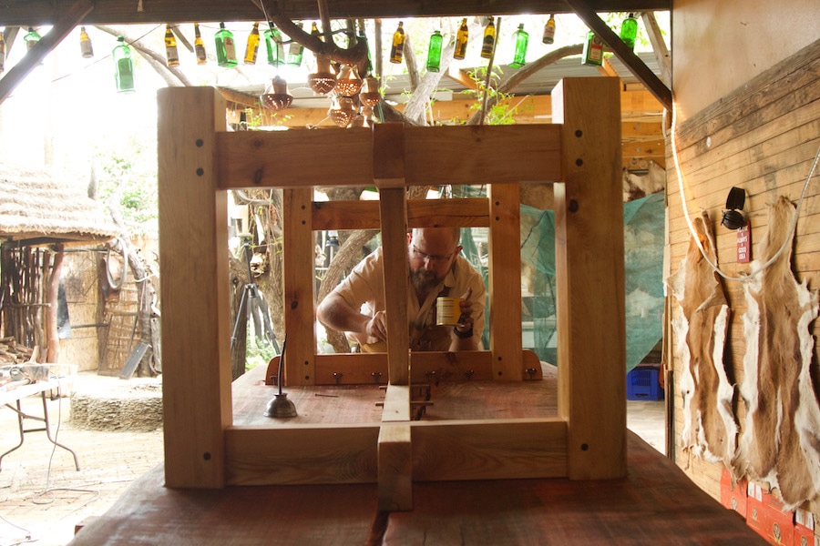
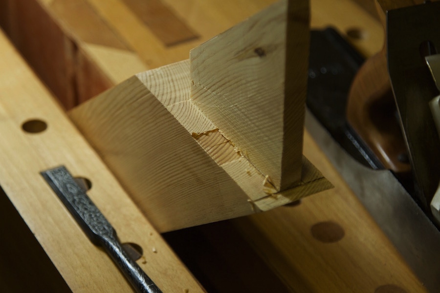
For the sake of trying something new I decided not to go with wedged through tenons as I did with the two workbenches that was built with similar sized stock. I am however partial to the idea of using wedges to ensure maximum strength. Therefore it was decided to experiment with wedges in a closed mortise. You will notice the kerf prepared for the wedge in the monstrous tenons. The sides of the mortise that needs to allow for the wedge to expand the tenon were adjusted. Then it is simply a matter of positioning the wedge in such a way that it sits in the entrance to the mentioned kerf while using pipe clamps to coerce the tendon into it’s mortise. That is of course followed by tapping the drawbore pegs home while the clamps are still in situ. The pictures below also show how I used my Festool Domino to cut the slots for the bits of wood that will fix the aprons to the top.
This was how the two leg-assemblies spent their festive season.
16/1/2017
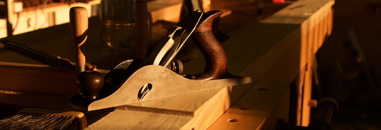
The drawbore pegs were then worked flush by sawing and hand planing.
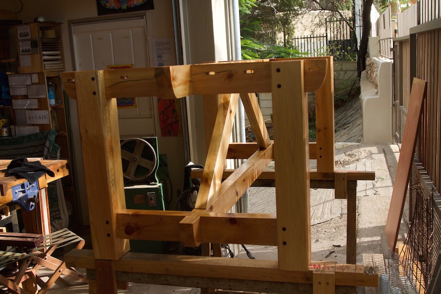
In order to mark out the exact location of the tenons of the two beams that link the two beams between the leg-assemblies (at an angle), I had to assemble the undercarriage.
By clamping the linking beams at exactly the right angle, I was able to mark out the shoulders of the tenons.
For some reason I found it very difficult to keep to the marked out lines while sawing away the waste by hand. It was the first time that I encountered this problem and still do not know exactly what was going on as I have done many similarly sized tenons in the same wood with the same saw?? Therefore I switched to the bandsaw for the rest of the work.
I usually like to saw close to the line and hone in on it by planing the cheeks to a perfect fit.
Marking out the location of the mortises.
15/3/2017
Drilling out waste.
Removed the rest of the waste by vertical chopping.
Then it was time for the final glue-up of the undercarriage. I was very happy with how it came together and it sure is a robust construction.
The undercarriage received a few layers of Woodoc.
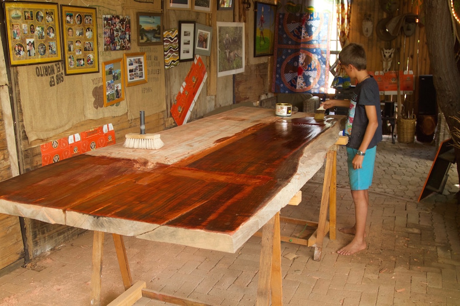
Before installing the undercarriage, the bottom of the top received a few layers of boiled linseed oil.
The pictures should do a better job than words to explain how the top was fix to the undercarriage.
Once that was done it became time to bring in some strength to get this baby to it’s feet.
Now I have to flatten the top by hand and trust me it looks a lot flatter than it is in the pictures below. I hope to complete this task before the end of the year.
No, this is not the title of a cheap porn movie aimed at the well known niche market for this particular genre of cinematic gems amongst serial tool collectors. The whole family should thus be able to digest this post, however JNSQ Woodworkings refuse to be held responsible for any unforeseen ailments that might result from indiscriminate consumption of the material. Parental guidance is therefore advised.
On a more serious note, I would like to apologise to my great friend, fellow blogger and tool historian par excellence Robert “Bob’s your Uncle” Demers for not posting this much earlier in the year. After all he found me a freakin legendary example of 20th century American tool manufacturing.
After using a couple of different examples of eggbeater drills it became apparent that my stockpile of African hardwoods necessitates contrivances with either massive drive wheels or a favourably geared two speed setup or ideally both. To give you an example, my first eggbeater was a Wiktor Kuc restored 1938 edition Miller’s Falls no. 2. It is supposed to be an ideal allrounder for the frugal (more recently known as “anarchical” in the prevailing Schwarzian vernacular) woodworker, but it really struggles to drive anything larger than a ¼” bit in lumber from the Dark Continent.
Initially I thought this is simply how it is with these eccentric drilling apparatuses, until by sheer chance I happened to stumble upon a two speed no. 5½ B Goodell-Pratt with a positively massive drive wheel. These babies know how to roll, innit. The GP has more torque than my 8 year old daughter, except in her case it is spelled slightly different.
Given this revelation I set out to procure another torque-ative eggbeater to torment my hardwoods with. Bob was of course my first port of call and I explained my predicament in some detail. You can read his summation of the tool here, which (by the way) is a hell of a lot more informative than this post. He agreed to keep his well educated eye out for a suitable monstrosity. It did not take him long to find Utopia in the form of a two speed North Brothers no. 1545.
Bob refused that I reimburse him for the tool or the shipment cost and sent it on it’s merry southward journey at the end of 2016. Luckily it did not embark upon a protracted sub-Saharan voyage like a particular parcel several moons ago. It arrived somewhat promptly, for trans equatorial pilgrimages, in mid January 2017. I did return the favour by sending him a locally made hammer, but clearly I received more value than he did.
It is only my second true North Brothers tool (as apposed to Stanley made attempts) and completely lives up to my very high estimation of this famous tool manufacturer. The low gear munches through anything Africa can throw at it and the considerable weight lends some advantageous momentum to drive wheel as well as a general feeling of old school quality.
The no. 1545The NB no. 1545 with the GP no. 5.5BThe NB no.1545 with a 1938 edition MF no. 2The NB no. 1545 with it’s smaller cousin the no. 1530
I took the drive wheel off and cleaned everything I could reach. It presently purrs like a cat on crystal meths.
Thank you Uncle Bob I will cherish this gem as long as I have the privilege to do so and hope to pass it on to someone who will continue to do so long after both of us joined the choir invisible.
My dear reader, I would like to apologise for my extended absence from the wonder world of virtual woodworking via the internet. You would find the reasons quite boring so let’s not waste any time nor effort ruminating on such drivel. This instalment of an apparently mammoth series will concern itself with the addition of the third and final layer of the so-called trapezoid leg. You can find earlier posts in this series here.
Seeing that the third layer would ultimately close up the internal workings of the whole construction, I took the opportunity to unscrew the second layer’s three ‘cross members’ (for lack of a better term). As you should be able to observe in the photos below, the old school mild steel wood screws received a coat of beeswax. This was accomplished by melting a block of wax in a small tin containing these traditional fasteners. The idea with this is that the wax should reduce the effort required to seat the screws and at the same time providing a layer that would resist future corrosion.
The screws were then seated after the surfaces that is supposed to be able to slide ever so slightly with the changes in ambient humidity over the years, were rubbed with beeswax. Whether this is useful (or possibly the opposite) I do not know, but I tried it anyway. Therefore I would urge you to ask someone who knows before following suite. Maybe some of our more experienced and properly trained cadres could assist in the matter.
Seeing that the plan was to fix the third and final layer using panel pins I had to fashion a custom punch to seat the nails below the surface of the wood. A short section of a round file which I picked up somewhere served perfectly well for this purpose. It was shaped carefully (not to take the temper out of the hardened steel) on a bench grinder to fit the head of the panel pin to a T. There are some picks further down to show the business end of my new redneck punch.
As is so common here in Africa, I also had to modify the panel pins somewhat to serve my purpose. In order to allow layer one and two to be able to move relative to each other, these panel pins had to stop short of layer one. In other words they should only fix layer three to the cross members of layer two. That was accomplished by snipping off the required amount, followed by resharpening on the bench grinder.
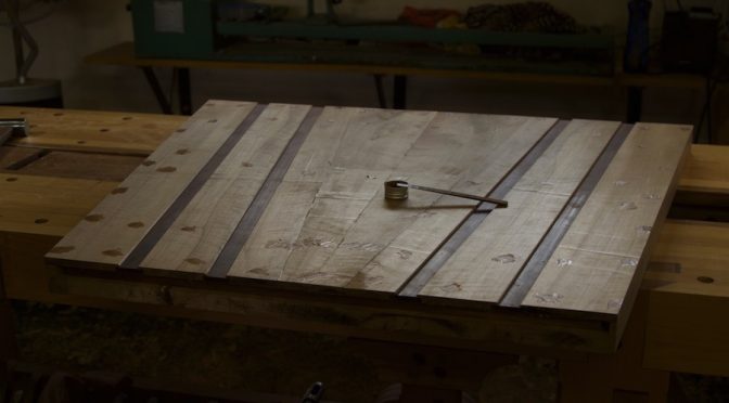
The two Kershout strips were fitted first, as they needed to be absolutely spot on given the fact that they mirror the spindles of the so-called Windsor leg. Kershout seems to enjoy spending time off the Janka hardness charts (literally and figuratively) so it hard to say where it rates in comparison to better known species, but let’s just say it tends to take exception when a nail wants to upset it’s feng shui. For that reason I had to drill shank holes for each panel pin, which allowed the shank through and only caught the slightly wider head. This way the panel pins were more inclined to retain it’s linear configuration and the Kershout refrained from flexing it’s muscles.
As discussed in earlier posts, the third layer only needs to add another 8 mm for the trapezoid leg to reach it’s intended thickness of 44 mm. Therefore I decided to challenge my new bandsaw with fairly wide re-sawing in very hard Witpeer. Of course that also allowed me to introduce visual interest by means of a book-matched arrangement of the various pieces.
In order to do that I needed one flat, square and twist-free face side and face edge.
The resultant 8 mm stock were then fitted from the centre of the leg towards the outside. I again used the hitherto unproven technique of rubbing beeswax on the surfaces that is supposed to be able to slide.
I used a no. 78 and a no. 10 Stanley rabbet plane to cut the rabbets that hides the space allowed for movement.
The book-matched pattern is already vaguely apparent.
All the sides were then worked flush.
By hand plane along the grain …
… and by track saw followed by hand plane across the grain.
The small cavities created by seating the panel pins below the surface of the wood were filled with a concoction conjured up by mixing very fine wood dust (of the same wood of course) and epoxy.
Once the elixir had time to set I did a preliminary round of surface preparation.
As you can see the book-matched pattern is starting to emerge nicely. Once it receives oil it should be positively stunning.
Even the opposite side is starting to display a certain je ne sais quoi.
The edges were then treated to some hand beading to hide the laminations.
As you can see it worked a charm.
In our next instalment we will move on to laminating the various boards that was chosen (many moons ago) for the top.
In January I became the very proud owner of an 18 mm pairing chisel made by the legendary Master Akio Tasai from Sanjo, Niigata. I have been eager to get my hands on one of these ever since I saw David Charlesworth discussing it on one of his Lie-Nielsen videos. He said something along the lines of: “This is a chisel made by a gentle by the name of Tasai and it gives me tremendous pleasure each time I look at it.” In that regard I cannot agree more with David, it is an absolute joy to use and look at.
Due to their considerable price and an unfavourable exchange rate, I have been confined to dreaming about one rather than buying one for several years. That made it so much more special when I finally got to handle a Tasai. As you can see, it comes in a pretty box decorated with Japanese gibberish (to the bovine amongst us anyway).
I have not come across a better made tool in all of my woodworking journey. As per usual for traditional Japanese chisels, it is made up of two distinct metal components. The back (or so-called mirror side) is composed of extremely hard blue steel that is especially made for Master Tasai. The rest of the chisel is made up of a much softer multi laminated steel. It is this Damascus style laminate steel that creates the aesthetic appeal of these chisels.
Unfortunately, I did not take a picture of the so-called “Ura” on the mirror side, but it is basically a very slight hollow that is meant to decrease the time spent on sharpening the chisel. Given this nifty design element I thought it would be a breeze to sharpen. That turned out to be a fantasy. It actually took a lot more effort to polish the back that anticipated, but I am sure the ura will speed up subsequent sharpening sessions.
As I said, this chisel looks impressive, but it’s true worth comes to the fore when it engages with wood. I made a few test cuts on the shoulders of these huge tenons. The shoulder lines were marked out with a knife so it was simply a case of feeling the cutting edge into these tracks and leaning on the chisel. It literally glided through the wood and left a superior polished surface in the end grain.
I have since used the chisel on African hardwood and it does not seem to shy away from the confrontation. If anything, it performed better in the hard stuff.
That then concludes my review of this work of art that happens to be quite a useful tool at the same time. I would say it is worth a lot more than what you find on the price tag.
This post disappeared from my site while it went into hiding. Here it is again for those of you who missed it.
Welcome back to JNSQ woodworking. Here is hoping that we will continue to share woodworking banter and ideas in 2017. This past weekend was my first back in the shop and it was a real joy. Much like 2016, my two main projects to focus on will be this so called “second commission” and the table for the shebeen.
7/11/2016
I will now report on the work done since our previous update in October of 2016. As usual just a quick reminder of what we are aiming for. A few shots of the model I built while developing the design.
Something that I omitted to illustrate in the previous post is the techniques that were employed to ensure that the spindles end up with zero splay. The first method makes use of a device that we shall call the Tambotie gauge (as I used a small Tambotie off-cut to create this fantastic piece of equipment).
The Tamboti gauge consists of an appropriately sized off-cut clamped to a square.
While reaming the mortises for the spindles you might remember how I made use of a stick with an appropriately sized tenon to check the rake angle.
The Tambotie gauge is used to check that there is zero splay by comparing the gap between the Tambotie off-cut and the spindle on both sides, as referenced off the side of the beam with the square. In this case the spindle is leaning ever so slightly towards the right.
Second of the two strategies again involves a highly complex jig that takes hours to build and set up. I clamped a winding stick to the side of the beam to check wether the spindle (positioned in it’s mortise) runs parallel to it, i.e. zero splay.
Once all eight mortises received this treatment it was time to test how the assembly would fit together. As you can see it came together nicely.
It is probably important to report on the stuff-up I made while drilling the pilot holes for the mentioned mortises. You might remember that I drilled one of these holes in the wrong direction and suffered from a Panic Attack subsequently. The solution I came up with was to turn a dowel of the same wood that fitted the hole perfectly and glued it into place. The hole was then drilled in the correct direction and the picture below show the result. There was only a small strip of the plug visible after drilling the new hole.
After reaming out the mortise there was no evidence left of the blunder on the surface that would be exposed to critical eyes once the tenon gets glued into position. In the pictures below you can however see the edge of the plug inside the hole. Eish, that was a close call. Woodwork has a way of keeping you grounded, isn’t it.
As these tenons run all the way through the beams, I decided to also wedge them. Here I am widening the mortise on the exit side to accommodate the wedges. I recommend reading Peter Galbert’s seminal work “Chairmaker’s Notebook” on how to orientate these spindles and wedges.
Next up I had to camouflage the laminations with a few carefully placed beads before glueing up the leg.
I used my pre-1900 no. 66 Stanley beadingtool, which I restored quite some time ago. It takes elbow grease beading such incredibly hard wood, but it is very satisfying nonetheless.
I think it accomplished what I intended as the beam now looks like a solid piece of timber.
The tenons were then prepared to receive the wedges.
Made some wedges …
… and prepared for glue-up.
I used a combination of mallet blows and clamps to coax the spindles into position.
Once they were seated to my liking the wedges locked them down for ever (I hope).
This is how the Windsor leg spent it’s December holidays, resting on the assembly table.
16/1/2017
This past weekend I continued my assault on the so called Windsor leg. I clamped it to the trapezoid leg and used the latter to mark out the final shape of the former. This way they are exact copies of each other in terms of measurements.
My daughter Aoife helped me to make the necessary cuts using my Miller’s Falls Langdon Mitre Box no. 75. It was quite a tricky operation given the awkward shape and size of the leg , but the Langdon made cutting the 9º angles straight forward.
One day the student will become the master.
The next big drama will be the third layer of wood that needs to be added to the trapezoid leg. I selected a good Witpeer (Apodytes dimidiata) board that ran pretty much through the centre of the tree and made a cut lengthwise along the pith. This gave me two quarter-sawn pieces. From these boards I then selected appropriate 800 mm chunks for re-sawing. The idea with re-sawing is to created a book-matched pattern to the inside of this leg. This layer only needs to be about 8 mm thick to get the total thickness of the leg up to 44 mm, which fits perfectly into my ratio of 22:44:66:88 mm (thickness) for the various parts of the table.
You will notice the two strips of Kershout (Pterocelastrus tricuspidatus) on top of one of the piles of re-sawn and planed stock. We will use those to create a type of depth confusion for an observer viewing the table from the Windsor leg’s end. This will hopefully enhance the effect of an construction that defies gravity, but you (and unfortunately I) will have to wait until the next post to see how this works or possibly not?? Here’s hoping (that it works, that is)!
You might already know that Je Ne Sais Quoi Woodworking almost disappeared into thin air, but alas it was revived albeit still in rehab. One day in mid January my site just vanished and it took days of work by the IT guy who set it up for me and my wife to work out what happened. I really do not want to go into the details of the traumatic event, suffice to say that it was an unsavoury experience.
I would also like to apologise to those who were looking for JNSQW and not being able to find it. A special thanks goes out to my two special blogger friends in Jonathan White (The Bench Blog) and Bob Demers (The Valley Woodworker) who tried to keep my spirits up. They both gave me lots of advice on how to solve the problem and prevent it in future. Thanks gentlemen.
What I have learnt though is that I do not know enough about the technical aspects of websites, wordpress, backups etc etc. I have now made it a mission to first get a better understanding of these vital bits and pieces. At present I am working through a series of videos on how to use wordpress in the best possible way and trying to work out how to optimize my photos before uploading it.
Another thing I realised is how much the blogging has become part of my life and therefore how much I missed it when the site went into hiding. I want to try and hang onto that thought to ensure that I appreciate being able to do it more and hopefully try to improve the quality of my posts and site. One of the tricks I have discovered so far is how to make time-lapse videos and post it on the site. Here is one to wet your appetite.
At least you can now look forward to quite a bit of material that heaped up in the meantime, which I now have to publish to get back on schedule. The two tables I am working on have both evolved significantly since my disappearance. It is wonderful to be back and I look forward to engaging with all of you on woodwork topics yet again.
This story starts way back in May when Jonathan White (of Bench Blog fame) sent me a William Marples Hibernia Mortise Gauge as a very generous, but completely unexpected present. You can read his and my posts on the tool for background. Anyway it got me thinking how I could return the favour. At the time I already met a delightful young Namibian blacksmith by the name of Hanno Becker. He trained in Germany through the ancient apprenticeship model they have for all craftsmen. Since he finished his training he moved back to Namibia and started his own business. He is a very refreshing change from the often money orientated younger generation. Hanno is driven by excellence.
Hanno and I decided in February to try and create our own version of a Japanese Daruma hammer that I wanted to use with chisels for fine joinery work. I have adopted David Charlesworth’s techniques for this type of work and a good purpose made hammer is essential. These Japanese hammers are so well thought out (over a matter of several centuries) and made that it is not just a case of rocking up and producing a good quality hammer, even with Hanno’s considerable and well polished skills. We wanted to have one perfectly flat face and one slightly convex.
By late June Hanno had the first prototype ready. You can see what it looks like in the picture below. By that time I had ample time to ponder over the shape and choice of wood for the handle. I wanted to create a handle that sloped towards the flat face of the hammer and away from the convex face. The idea behind this is to open the convex face up to keep one’s knuckles away from the work when setting nails, hence the convex design of the face. The curve towards the flat face helps keep the face perfectly square on the butt end of your chisel while doing precision joinery work, hence the flat design of the face.
This picture illustrates one of the most challenging obstacles in producing these hammers the traditional way. As the blacksmith forms the hole for the handle it deforms the shape of the billet.This picture illustrate the ergonomic advantage of the sloped handle while doing joinery work with the hammer.
I made my first handle and used the hammer for a week before handing it as a present to my cousin the Urologist. Apparently he has been using it to chisel out prostates ever since. Apparently it works like a dream, albeit a particularly frightening one.
My apprentice Connor is helping me to shape the handle.The handle gets wedged in two directions. First a wooden wedge longitudinally, followed by purpose made metal wedges diagonally with regards to the aforementioned.
A trick I learnt from Hanno is to heat up (ever so slightly of course as not to have an effect on hardness or tempering) the head and rub on beeswax. It creates an attractive protective finish that smacks of the old artisan age.
What I learnt from this first attempt is that the handle needs to fit perfectly in the head otherwise you end up with the metal wedge splitting the handle below the head. There is a learning curve to everything in the shop I guess.
Another advantage of the handle curving towards the flat face is that it can be placed on the workbench like this while doing joinery work and it is easy to pick up immediately in the desired orientation to continue working. The curve and oval shape of the handle also informs the user immediately which face is at the business end if picked up without looking at the hammer.
After this first prototype Hanno and I collated our thought on where we could improve the design. What we notice on the positive side was that the hammer is an absolute joy to use. Clearly the age old tradition of hardening only the faces and keeping the rest of the head relatively “soft” works wonders for the feeling of superior power transfer and pretty much eliminating recoil. When I first read about this in Japanese hammer literature I thought it was just hype or marketing, but believe you me it is quite striking (pun intended) when compared to a regular commercially made hammer. I noticed that one needs to use the hammer for a little while before the mentioned effect reaches a peak. All I could think was that it has something to do with the “joint” where the wood meets the metal. It seems as if it needs to settle or mature a bit.
It might have something to do with the properties of the Assegaai (Curtisia dentata) I chose for the handle. Allegedly it was the species favoured by the Zulus for their spears, hence the common name of the species. Assegaai was also heavily favoured by colonial wagen builders, especially for the spokes of the wheels. Assegaai is extremely fine grained and hard, yet surprisingly flexible. Another prized property is the fact that it tends to be extremely stable once well seasoned. A property that is priceless to keep the spokes secured in their mortises and would probably apply to the joint with the metal head. I think it has something to do with these properties of the Assegaai which translates into a joint with the metal that needs a bit of time to settle to give a very noticeable improvement in the feel of the hammer. In conclusion we thought the first prototype was a resounding success, but wanted to see how much better it can get.
We decided to try and aim for a artisan round (as apposed to perfectly round) shape to the head, improve on the inside shape of the hole through the head to increase the grip of the handle, and I wanted to create a more flowing look to the curve of the handle. Hanno then invited me to his shop on a Sunday to witness the process firsthand. At this stage he had already made two more heads and thought he was ready to produce a winner.
This is one of the two heads Hanno made in phase two.
On the big day Hanno first made a new chisel for punching the hole through the billet. He developed a few ideas on how to improve the chisel from the first two phases. This chisel is made from a special type of steel that is ridiculously hard in order to punch a hole through the special steel that Hanno handpicked for the hammer’s head. The chisel tapers slightly to ensure that the hole first narrows over the first third and then flares out after that when approached from the end where the handle enters. This feature together with the wedges ensures a very sturdy joint with the handle.
Once the chisel was done he moved on to the billet.
The hole gets punched through the billet from both ends bit by bit. It was at this stage that I realised just how skilful this young man is.
As you can see, this process tends to deform the billet somewhat.
One perfect hole done and dusted.
At this stage it takes even more skill to regain the round shape without deforming the hole.
A week later Hanno delivered what would become my bench hammer and it looked liked this. My Jenesaisquoi Persuader (as apply named by Matthew J McGrane on Bench Blog) has become my favourite tool, it is literally the only tool that does not have a dedicated storage spot as it lives on the bench. I use it constantly to set my holdfasts (with the domed face of course) and it is a revelation in tandem with my Lie-Nielsen chisels while doing joinery work. Now I only need a Akio Tasai chisel to go with it. If there is one outstanding feature of this hammer that gives me tremendous pleasure (ala Charlesworth) each time I use it, it would be the incredibly soft efficiency of the power transfer. When hitting a holdfast there is almost no discernible recoil.
28/11/2016
By late November I received two hammer heads representing phase four of the development. By now my handle shape improved to a more pleasing curve and I picked the best cuts of Assegaai I could lay my hands on.
Below you can see my hammer’s handle. (i.e. phase three)
The following photos illustrate the improvements we identified for phase four. We wanted to increase the size of the hammer’s sweat-spot by increasing the diameter of the cylinder shaped head, while retaining the weight of approximately 375 gram. That necessitated the head to become a bit shorter.
The phase three hammer is on the right and the phase four on the left with a noticeable increase in diameter.
Again phase three on the right and phase four on the left. Roughly the same weight yet noticeably shorter.
I try not to fuss too much when making these handles as they are meant to be working hammers not museum pieces. I also used the set of tools that I imagined an old artisan from yesteryear would employ for this task. That is perhaps with the exception of the electrivorous bandsaw that was initially used to cut the curves, but was followed by drawknife, spokeshave, card scraper and finally sandpaper. As my talented friend picked up in his assessment of the hammer, it actually balance best when you choke up on the handle somewhat. This is also intentional as that is the grip one would use when doing precision chisel work (illustrated by the picture below). When setting nails or holdfasts the balance is less important.
The wooden wedge.
Followed by two (another detail we added) rather than one purposed made metal wedges.
From right to left, phase 2, phase 3, and finally phase 4.
And here they are in the opposite direction, with phase 2 on the left and 4 on the right.
Finally they received a coat of Ballistol. I prefer using only a light coat of oil as it retains a better grip and tends to be less sweaty compared to lots of coats of varnish.
Then I sent them on their merry way to Washington and Nova Scotia. They are presents for my two blogging friends Jonathan White and Robert “Bob’s your Uncle” Demers. I hope you guys get as much joy out of them as I do.
It is that time of year once again, to take stock of what happened in the Je ne sais quoi Woodworking shop during the past 11 months. As usual I will add links to the posts I wrote on all the projects in this annual inventory.
I started off 2016 with small projects to improve the shop and built a few key tools that would come in handy later in the year. This mitre box and saw did not need much rehabilitation, but did suck up a few hours to set up and tune. My good friend Bob Demers guided me through the process of tuning the saw for the mitre box and wrote an epic treatise on the topic. It is as easy as Falling out of a tree, if you know the principles.
After using my new bench for almost a year by January 2016, I made a few small adjustments. So far the bench is working exactly as I hoped and I am using 95% of the design features. Therefore it seems that the bench fits well with my particular way of working.
The most important project of the year actually started in 2015 already and will clearly extend into 2017. It is a table for friends of ours. In January I put pen to paper for the first time in terms of formalising the design that evolved during countless hours of reverie since about mid 2015. I applied some of the basic principles employed by artisans from the pre-industrialisation period in terms of ratios and proportion. The design was otherwise inspired by the work of George Nakashima and Japanese joinery in general. I chose this genre as it compliments the the wild nature of the wood I have in my collection. After nutting out the key proportions of the design on paper, I tested the concept design by building a small prototype. This process led to further tweaks to the design, the most drastic of which was a redesign of one of the two legs. I came up with a so called Windsor Leg design.
You can read the series of posts on this project here.
A saw vise has been on the list of things to buy for a few years by early January 2016. In the process of discussing options with Mark Harrell of Bad Axe Tool Works he advised me to build my own rather than look for a vintage model. He also pointed me towards a design by Jason Thigpen, which became the inspiration for my version.
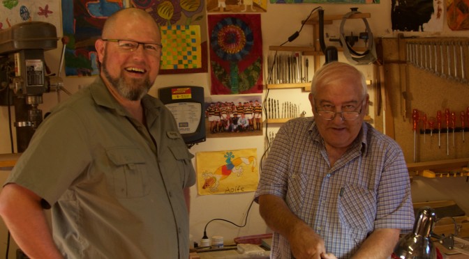
This year I was also very fortunate to be able to work with my father while he visited briefly. We worked on a bed for my daughter.
Aoife’s bed is also based on Japanese design and joinery. The main structure was made out of reclaimed Scots Pine and the headboard from Without (Cape Holly or Ilex mitis). This was the first project where I used dovetail keys to stabilise cracks in a feral board.
In May we spent a week on the island of Kho Samui in Thailand. While there we did a cooking class with a wonderful lady by the name of Ying. She inspired a few unplanned projects.
The other major project of 2016 is the table for the shebeen. I am in the process of using a massive slice of Rose Gum for a table top furnished with a heavy reclaimed Scots Pine undercarriage. A few readers have commented on the robustness of this table. The reason for this is that when the brave warriors of this fair land descend on a humble shebeen, they do not tend to take any prisoners. That is why you hardly ever find any furniture in a hundred meter radius from a shebeen. To survive in such a harsh habitat, a table needs to be overbuilt to the extreme.
A wonderful 2016 addition to the Je ne sais quoi team came in the form of Cape Town based woodworker Frank Bartlett. Frank started writing on a few of his legendary projects and it has been very well received. I want to thank Frank for his contribution and hope to continue working together for many years. Our aim in this regard is to create a a space where woodworkers from Africa can publish posts and hopefully become a hotspot for networking. In short, we want to put African woodworkers on the map.
We might have a new cadre in the form of another talented Capetonian by the name of Werner Schneeberger in the very near future. I am privileged to have seen some of his work already so can attest to the quality. Werner we look forward to your contributions in 2017 brother.
The absolute highlight of 2016 was when Je ne sais quoi Woodworking were chosen as one of the five most nominated hand tool orientated blog sites by the Woodworkers Guild of America. It was a huge honour and I would like to thank all our readers who went through the trouble of nominating and voting for us. It realy helps to know that there are people out there who support JNSQ Woodworking.
The title picture of this post is meant to remind you of what my shebeen looks like. The beautiful ensemble of chicks in the picture demonstrate how happy they can be around a stove. For fear of mass feminist hysteria, I will leave it at that.
It is a case of onwards and upwards with this project, which reminds me of something I have noticed in terms of my woodworking journey. Since about July this year I seem to have entered the next phase in my woodworking. It took the best part of 5 years to set up my shop in such a way that I can build furniture using a set of tools that suites me. That entailed lots of fairly small projects such as building various hand tools and jigs. There were of course also a smattering of mammoth projects such as building the two Roubo-esque workbenches, but it the predominance of small projects made it easy to blog regularly.
More recently however I have started working on projects that is destined to spread it’s wings and leave the shop for good (once finished of course). These projects seems to be more of a war of attrition than blitzkriegs, which makes it harder to find ways to blog regularly. As my friend Jonathan White (from The Bench Blog) usually say (and I am paraphrasing here), posts should rather be infrequent than of substandard quality.
OK enough of my introspective reverie and on with our topic at hand. Didi and I managed to finish the stage of inserting the monstrous Kershout Dutchmen along the crack in the top. They were worked roughly flush with my shop made scrub plane. The top was then moved to the shebeen to keep it from getting wet when the rainy season arrive. I took great care to set up the sawhorses in such a way that the top would stay wind free.
Luckily I checked with my winding sticks whether the aprons and stretchers were still wind free before continuing with the joinery. I found that they twisted slightly since being planed to perfection a few weeks prior. So back to the bench they went for some more remedial action. I find that my Lie-Nielsen low angle Jack plane with it’s toothed blade works well where you encounter significant knots like in this case.
The mortises were then marked out and the waste removed with a spade bit driven by an electrivore.
In this case the eletrivore was assisted by a carnivore, which is inevitable being resident in Namibia for several years. Vegetarianism (vegans are already extinct here) appears to be illegal (and omnivorous creatures should not get too cosy either) in this fair land and ‘vegetables‘ is certainly a most deplorable swear word.
25/10/2016
The rest of the waste were chopped out using chisels and a hammer.
Next up were the two beams that connect the two leg assemblies.
This is what the shop floor looks like after serious hand planing (in 35 degrees celsius weather I might add).
Aoife came for a visit to the shop and took some photos. Her right hand is not nearly back to normal (after the drama we had in February), but managed to get a few in focus.
These long beams slot into each apron/stretcher with a type of cross lap joint. In the pictures below I am marking out the exact location of the slot in the stretcher/apron.
Followed by cutting the slot, …
… which allows the two parts to lock together.
I then drilled the holes for the drawbore pegs. As you might remember I like producing my own custom dowels for this purposed. I prefer using Assegaai (Curtisia dentata) for this as it has all the ideal properties. I use a Stanley no. 77 dowel machine with a ½” cutter head. In the pictures below I am using a ½” brad point drill bit to mark the exact location of the holes in the leg on the tenons of the stretcher/aprons. This mark can then be used to offset the hole through the tenon. Basically you move the hole through the tenon a smidgen closer to the shoulder, which allows the peg to draw the tenon into the mortise when it is driven home.
In these pictures I am busy chamfering the edges of the legs using two block planes. The one is tune to take heavy shavings and the other for very light shavings. The bulk of the timber is removed with the heavy cuts followed by a few fine cuts to leave a perfect surface. I simply run two lines parallel to the edge and plane to the line. Doing this task by hand is one of the most therapeutic in my experience.
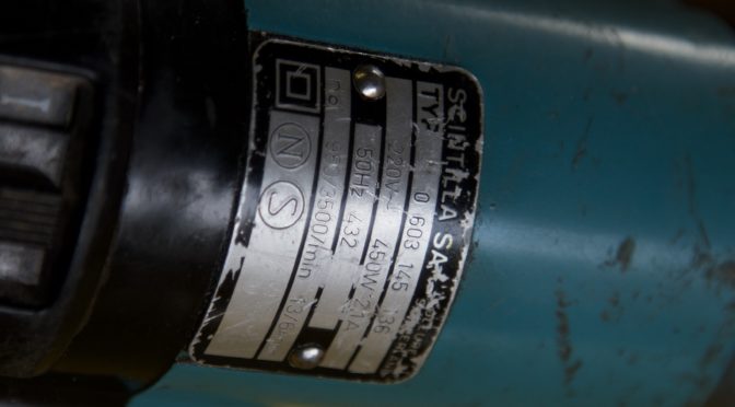
As I have written ad nauseum in the past, Namibia is not a particularly Utopian wasteland for tool collectors. It was thus with some surprise that I found this old Bosch drill in quite an exceptional condition at an Antiques Shop in Swakopmund. I already have two old corded hand drills given to me by my father, but wanted to buy this one for my son. At the equivalent of US$36 it was not going to break the bank either, so why not?
Clearly this drill seems to be from an era prior to the dark blue and green colours used by Bosch in more recent years. What I want to find out from all you tool aficionados is, how old is this drill and would it be considered to be any good? Yes Bob I am referring to people like you who has an embarrassing amount of knowledge on tools of any description.
It has “Scintilla SA” and “Switzerland” on the metal label. Maybe that helps.
I would appreciate any info to help know a bit more about the history of these drills.