Category Archives: Bench accessories

Upgrades to my split-top Roubo bench

21/1/2016

It is almost a year since I finished my first Rouboesque bench, which gave me ample opportunity to see which design features works for me and which does not. One of several reasons (discussed in detail in this post) why I decided to go with a split-top design was to be able to have easy access to clamp work using f-style clamps along the centre of the bench. I therefore sized the sliding tool trays in such a way that there would always be gaps between them for the above mentioned clamping activities.

What has become apparent over the past year is that although this is a very handy feature I do not need it all that often due to the number and positioning of the holdfast/dog holes. I am able to use holdfasts for 95% of that type of work holding. To add to that, the gaps between the sliding tool trays constantly threaten to swallow tools which the end up crashing into the planes on the shelve below the bench top.

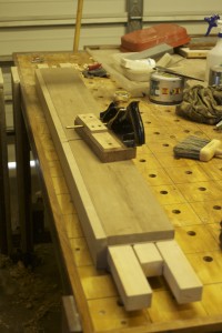
For these reasons I came up with a fairly easy solution. I made two gap fillers that can easily be removed. The pictures should make it clear how it works. The bigger one of the two now act as a more traditional type tool tray that can hold plenty of tools below the surface of the bench top. These gap-fillers do not interfere with the sliding tool trays at the top, which can still slide to expose the tool trays below them.

I hope that the series of photos that follows will make it clear how these minor tweaks prevent the bench from swallowing tools yet retains easy access for clamps when needed.

IMG_6007IMG_6008IMG_6009IMG_6010IMG_6011IMG_6012IMG_6014IMG_6015IMG_6016IMG_6017IMG_6019IMG_6020IMG_6022IMG_6024

Holdfast boots

18/5/2015

As self-proclaimed leader in the field of woodworking haute couture, I would like to introduce the next frontier in menuisier fashion. Last week the four Gramercy Tools holdfasts that I ordered arrived  after 5 weeks of traveling across time zones, an ocean and the equator. Holdfasts work like a charm, but tends to mar your work unless you stick a bit of scrap between it’s fangs and your stock. It can be a bit of a hassle so I thought of a way to address this particular issue.

I like to do leather work from time to time and it made sense to use this skill to alleviate the problem. As you can see in the pictures below, I custom-fitted these stunning Almond-toed leather booties to the business end of the holdfasts. I used two layers of Skeleton Coast seal skin for the sole and free range Namibian cow’s hide for the upper. It would not look out of place on a catwalk in Milan (says he), but I am not sure whether the common adage used to describe particularly sexy boots would necessarily apply. Apart from the obvious visual appeal, it has real functional advantages as well. It improves grip, protects your stock and cuts down the time spent fiddling with bits of scrap wood.

IMG_4444IMG_4445IMG_4447IMG_4446


I also took to the shaft section of the holdfasts with a rasps to improve it’s grip. It works like magic.

IMG_4450IMG_4451IMG_4448IMG_4449

Below you can find some examples of the boots in action. The pictures also provide ample evidence to support my decision to ignore Monsieur Schwarz’s Commandment to stick to very few dog/holdfast holes.

IMG_4452IMG_4453IMG_4454IMG_4455IMG_4518IMG_4524IMG_4528IMG_4540IMG_4535

Here are a few examples of a saw bench modeling the trend-setting footwear.

IMG_4456IMG_4457IMG_4458IMG_4487IMG_4488IMG_4491IMG_4492

My bench holdfasts live here.

IMG_4459


So there you have it, once again the best of tres chic woodworking. Only at Je ne sais quoi Woodworking.

My 18th Century Workbench in progress 29

23/2/2015

Since being part of the Woodspotting family I started reading Joshua A. Klein’s blog, The Workbench Diary. It is highly recommended, by the way. A while ago he wrote a series of posts with advice for woodworking bloggers. I realised that I tick almost none of the points he mentioned.

The point which is relevant to this post is that he recommended that one should post photos of yourself on a fairly frequent basis. I realised that I have posted almost no (such) picture at all. Apart from the Freudian look on my home page of course. My daughter Aoife (6 yoa) took to the camera this weekend, thus providing me with some material to scare off potential readers. I recently heard someone say about another person: “He has a face for radio and a voice for the printed media!”. I wonder whether Joshua considered this issue in writing his blog guidance? Maybe some of us should rather stick to pictures of old Stanley’s and dovetails.

Anyway, into the fray!

IMG_3284IMG_3285

By now you might want to pray (just to make it today!) …

IMG_3292IMG_3293IMG_3289

… fair enough, let’s get back to woodwork. Here you can see the first fit of the Roubo-esque sliding-deadman-cum-eggbeater-leg-vise.

IMG_3299IMG_3300IMG_3301IMG_3302IMG_3304IMG_3305

… and the same beast after some oil. You might notice the candle wax I applied as a lubricant. It works like a charm. As you can see, it is quite easy to remove the jaw and it becomes a conventional sliding deadman when necessary.

IMG_3312IMG_3313IMG_3314IMG_3315IMG_3316

It did not take too long for it to start paying rent.

IMG_3324IMG_3325


Cheers

Gerhard Marx

Dog maker

9/2/2015

My nearly finished workbench needs a profusion of dogs. In order to speed up the production and have some degree of consistency, I made this dog maker out of a scrap piece of beech. It has a multitude of “high-tech features” such as:

IMG_3151

1) Self-tapping screw to hold the stock in position.

IMG_3152

2) A hole for drilling the bullet catch hardware hole.

IMG_3156IMG_3161


3) A kerf to saw a flat face (leaning 2º forward from the vertical position, ensuring that the upper most tip would touch stock first)

IMG_3153IMG_3162IMG_3163

4) A kerf to cut each dog to the exact same length.

IMG_3154IMG_3155

That is followed by a few more steps, once the dog is liberated from it’s maker. The pictures tells the story.

IMG_3157IMG_3159


IMG_3160IMG_3164


IMG_3165IMG_3166IMG_3176IMG_3227

My 18th Century Workbench in progress 27

9/2/2015

On Friday afternoon I finally fitted the planing stops. It must be at least 3 months since the Ysterhout scraps were laminated. During the coarse of these months, I had several different ideas as to how the planing stops should be kept in place. In the end I simply went with a very tight friction fit. In other words, you take a mallet and bliksem (colloquial Afrikaans meaning many things, depending on the context, in this particular case ‘clobber’ comes to mind) them in and out of their little nest. So far it works like a charm, but I will report on how it turns out in the long run.

I decided to place the planing stops in front of the leg vise, rather than behind it as seen in most traditional benches. This shortens the bench surface available for planing, but also means that most of the planing can be done without having to lean over the leg vise. For longer boards I will eventually have a stop at the very end of the bench as well.

IMG_3113IMG_3114IMG_3115IMG_3116IMG_3117IMG_3118IMG_3119IMG_3120IMG_3122IMG_3123IMG_3124IMG_3126IMG_3127IMG_3131IMG_3132IMG_3133

During the course of last week, I moved all my bench planes to their new address. You will notice that some of them have leather sleeping bags to stop them from collecting excessive woodworking debris. I am slowly stitching these by hand during weekends away from the shop.

IMG_3143IMG_3135IMG_3137IMG_3138IMG_3140IMG_3141

The idea all along was to fit a traditional crochet to operate in tandem with the leg vise, but last week I saw this idea on another blog (unfortunately I can not remember which). I simply drilled four x 3/4″ holes in the side of the top beyond the leg vise. A simple Assegaai dog can now be used in the appropriate hole as a stop.

IMG_3167IMG_3168IMG_3169IMG_3170

This weekend was actually the first opportunity to use my new bench properly. In the pictures below you can see how it assisted in an array of different ways to do bread-and-butter type operations. I am working on a sliding deadman for each side of the bench.

IMG_3145IMG_3171IMG_3172IMG_3173IMG_3174IMG_3175IMG_3176IMG_3177IMG_3178IMG_3179IMG_3180IMG_3181IMG_3182IMG_3183IMG_3184IMG_3185IMG_3186IMG_3187IMG_3188


IMG_3197IMG_3198IMG_3199IMG_3200IMG_3201IMG_3218IMG_3220IMG_3221IMG_3222

I wrote a separate post on this shop made beader, which you should find in the recent posts section. I added the beads to hide the laminated nature of the stock that makes up the deadman.

IMG_3223IMG_3224IMG_3225IMG_3226IMG_3228IMG_3229IMG_3231

My 18th Century Workbench in progress 26

2/2/2015

On Friday afternoon I turned plugs for all the holes created in the bench top to attach hardware. They were then glued in overnight and worked flush to the top first thing on Saturday.

IMG_3063IMG_3064IMG_3065IMG_3066IMG_3067IMG_3068IMG_3070IMG_3071

Initially I had plans to build quite elaborate sliding tool trays to occupy the space between the twin-top of my bench. After lots of thought I decided to first build very basic trays in order to get an idea of what I really need by using them for a while. This train of though produced these Masonite and Tasmanian Blackwood trays held together with 32 self-tapping and four traditional wood screws (each).

As you can see there are five trays in total. There are three that operate in the top groove and two in the bottom. They slide effortlessly to enable the bench user to be able to open up space when he/she would like to use F-style clamps through the split in the top. They also provide a very handy storage option for the bread and butter tools that are constantly used at the bench.

I made lids for the top three trays to prevent unwanted debris from nesting in them. The bottom two trays hide under the top ones, so they do not need lids. The top surface of the lids sit roughly 3 mm below the top of the bench, which creates a handy area to place tools that might want to roll off the bench. This is illustrated in the pictures by the Yankee screwdriver.

IMG_3073IMG_3074IMG_3075IMG_3082IMG_3083IMG_3085IMG_3086IMG_3087IMG_3088IMG_3089IMG_3090IMG_3103IMG_3104IMG_3105IMG_3106IMG_3107

The building phase of this project had it’s first birthday on Sunday the 1st of February. I managed to apply the first coat of finish only hours before the celebrations. For this purpose I prepared a 1:1:1 mixture of Tung Oil, Mineral turpentine and diesel. From my reading it seems as if wood borer (which frequents this particular neck of the woods) loves beech, so I though the addition of some diesel might persuade them to seek alternative pastures. In the pictures you can see how it made the Kaapse Swarthout, Witpeer, Ysterhout and Assegaai come alive, while It gave the beech a very slight amber tinge. It was followed up on Sunday with a coat of Wooddock. You might notice that I did not apply any finish to the top as it still awaits it’s final flattening. The plans is to use a Tung Oil and Varnish mixture for the top. Please note that it might be useful not to sand between coats as it creates a grippy texture, which is desirable on a workbench.

IMG_3076IMG_3079IMG_3080IMG_3081IMG_3091IMG_3093IMG_3094IMG_3095IMG_3096IMG_3097IMG_3098IMG_3099IMG_3100IMG_3101IMG_3102IMG_3103

My 18th Century Workbench in progress 25

November 2014

My final job towards finishing my bench for 2014 was to start building the twin screw vise jaw. I managed to prepare the two beech boards (pictured) by hand a month or so earlier. Thus it had quite some time to settle. Lie-Nielsen provide a very detailed pdf document on how to build the jaw that goes with their hardware. It took some work with the router, a glue-up and Bob’s your Uncle!

IMG_2689IMG_2690IMG_2691IMG_2692IMG_2693IMG_2694IMG_2695IMG_2696IMG_2697IMG_2698IMG_2699IMG_2700IMG_2701

19/1/2015

I decided to take a few pictures to document the state of the bench prior to any work done for 2015.

IMG_2943IMG_2944IMG_2945IMG_2946IMG_2947IMG_2948IMG_2949IMG_2950

2015 started off with some very tricky fitting work in order to get the twin screw vise fitted to the bench. The main reason for this is that I decided to drill holes in my 4″ bench top to accommodate the 2 ACME threaded rods, rather than to cut 2″ deep dados.

The Witpeer breadboard end had to be sawn off flush with the edge of the top before I could even start to fit the vise.

IMG_2999IMG_2998IMG_3003IMG_3004IMG_3005IMG_3006IMG_3007

I did not take too many photos (during installation) as I was too busy swearing and struggling, but here are some pictures of the end result.

IMG_3008IMG_3009IMG_3010IMG_3011IMG_3012IMG_3013

26/1/2015

This weekend I focused on getting the end vise finished.

IMG_3016IMG_3017IMG_3020IMG_3021IMG_3022IMG_3024IMG_3077IMG_3078IMG_3025IMG_3026IMG_3027IMG_3028

Then I made the two handles for the other two vises, using Assegaai and Beech.

IMG_3029IMG_3030IMG_3031IMG_3032IMG_3033IMG_3043IMG_3050IMG_3051IMG_3052IMG_3053

Here are my first shop made Assegaai bench dogs in action.

IMG_3059IMG_3058IMG_3054IMG_3055IMG_3057IMG_3061IMG_3060

It is done!!!

12/10/2014

Well, not quite, but it is glued up!!! And that before the humidity changed. At 15h30 on the 12th of October 2014, my wife and I started assembling the bench. It was a very stressful 2 hours, but now I can relax and work at my usual leisurely pace.

I will soon have some better photos, but here are a few to wet the appetite.

photo 1photo 3photo 4


My 18th Century Workbench in progress 20

15/9/2014

I started off the weekend by using my no 78 Stanley rabbet plane with it’s sexy (yeah right) shop made fence to shape the moulding at the top of the long stretchers. The moulding has three primary functions. It aims to hide the fact that it is a laminated beam of Witpeer. You will find that the two small steps are placed to hide the lamination line on the side of the stretcher.

IMG_2207IMG_2208IMG_2174IMG_2175IMG_2211IMG_2212

The chamfer I am working on here creates a v-shaped surface for the foot of the sliding deadman to slide on and hopefully adds some aesthetic value too.

IMG_2187IMG_2188IMG_2189IMG_2190IMG_2191IMG_2198IMG_2199

Here you can see the array of planes used the create the moulding.

IMG_2235IMG_2203IMG_2201IMG_2200IMG_2202

I then moved on to seating the twin screw vise stand offs. The 30 mm diameter holes meant to accept the ACME threaded rod were already drilled through the top a week or so ago. I used an electric hand drill with a spade bit to remove the bulk of the waste before chopping the rest out with my Lie-Nielsen ½” mortise chisel.

IMG_2182IMG_2183IMG_2185IMG_2193IMG_2192IMG_2194IMG_2197IMG_2205IMG_2206

That got me this far.

IMG_2210IMG_2209

The electric router removed most of the waste for the shoulders (so to speak) of the stand offs. I then used the router plane pictured to dial it in to the exact depth.

IMG_2213IMG_2214IMG_2215IMG_2218IMG_2217IMG_2222


IMG_2221IMG_2226

The result.

IMG_2223IMG_2225IMG_2227


Next I marked out and drilled the holdfast holes in the legs on the drill press. You will notice that the ¾” holes are relieved to 1″ from the back of the leg.

IMG_2229IMG_2230IMG_2231IMG_2232

IMG_2233

My 18th Century Workbench in progress 18

27/8/2014

Last night I sat down to design the chop of the leg vise. I wanted to come up with something fresh that I have not seen before, yet without compromising on the function of the chop. The pictures below show my freehand concept sketches. You will have to wait until we build the chop to see how we create this appearance. I still do not know myself, but time will tell. I will add the photos of how the chop develops to this post as it happens.

IMG_0159IMG_0160


8/9/2014

Here you can see how I processed some beech using my band saw and planer. I am aiming for a chop that is about 2″ thick after laminating these strips.

IMG_2089IMG_2090IMG_2091IMG_2092IMG_2093IMG_2094

In order to lose as little thickness as possible I hand planed one edge of each strip flat and used that as a reference surface to guide my Festool Domino. The dominos help to keep the reference edges flush during the glue-up.

IMG_2095IMG_2096IMG_2097

I arranged the strips as pictured with attention to it’s end grain.

IMG_2098IMG_2099


In these pictures you can see how my assembly table and a few clamps assisted to hold the strips while cutting the domino slots.

IMG_2100IMG_2101IMG_2102IMG_2103


My skill to and method of lamination has improved significantly as a result of the shear volume of lamination required during this project. I use my shop made proletarian sanding contrivances loaded with a range of different grit sandpaper (120, 150, and finally 240) to remove machine marks from the glue surfaces.

IMG_2105IMG_2107IMG_2106IMG_2104IMG_2108IMG_2126IMG_2128


After flattening one face of the laminated stock with a range of hand planes it was used as a reference surface in the planer to flatten the opposite face. I then marked out the curves, drilled the holes for the vise screw etc etc.

IMG_2135IMG_2136IMG_2137IMG_2139IMG_2140IMG_2138IMG_2141


Here I removed the bandsaw ripples with my Lie-Nielsen block plane followed by some attention from the proletarian sanding contrivances (aka sanding planes).

IMG_2142IMG_2143IMG_2144


Then I started shaping the chop as pictured using my late 19th century Buck Bros. drawknife followed by a series of rasps and files.

IMG_2145IMG_2146IMG_2147IMG_2148IMG_2149IMG_2150IMG_2151IMG_2152IMG_2153IMG_2154


6/10/2014

IMG_2291IMG_2292IMG_2293IMG_2294IMG_2349


3/11/2014

A quick dry fit with the bench assembled.

IMG_2574IMG_2575IMG_2576

Here I prepared the tenon for its two wedges.

IMG_2579

I shaped the top of the jaw at an angle. I thought I would first use the vise for a while, before trimming it flush to the top of the bench. That way it has some time to settle.

IMG_2580IMG_2581IMG_2582IMG_2583IMG_2584

The toe was shaped as pictured.

IMG_2588IMG_2589

I chose Namibian Skeleton Coast seal bull leather to add grip to my leg vise. It is incredibly tough stuff.

IMG_2585IMG_2586IMG_2590IMG_2591IMG_2592IMG_2593

This is officially my first attempt at carving.

IMG_2594IMG_2595

The chop was glued into position using the pictured method to ensure that it is lined up absolutely spot on.

IMG_2600IMG_2601IMG_2602IMG_2603IMG_2604IMG_2605IMG_2606IMG_2607

Now this next process took some time to find a solution for. I decided to add leather to the leg as well, but wanted it to remain flush with the rest of the front of the bench. Therefore I needed to remove wood (about ¾ of the thickness of the leather) in the area where the vise jaw touch the bench and leg. It was quite a mission, but I finally managed to do it with the help of my router plane.

IMG_2596IMG_2597IMG_2608IMG_2609IMG_2610IMG_2611IMG_2612IMG_2613IMG_2614


This way the leather becomes flush with the front of the bench once some pressure is applied by the jaw. So far so good.

IMG_2627IMG_2632