As promised, we will start looking at what makes this legvise different to others in this chapter. For one thing, I do not know of any legvise that sports an Ysterhout parallel guide. If you are interested you could read more about Ysterhout’s properties in my post on my assembly table. (www.jenesaisquoiwoodworking.com/alternative-workbenchassembly-table-chapter-four)
This process might well seem a smidgen confusing, but I show the process as close as possible to how it happened. It means that various parts gets worked on all at the same time and we discuss only the small step that was taken at that time then jump to the next part and return to the previous part at some point in the future. If you do woodwork I am sure you will understand this haphazard methodology.
In the pictures below you can see how I laminated two pieces of ysterhout to create the beginning of a parallel guide.


The area I removed here was done on the table saw. The idea was to use this design to provide ample structural strength to the joint with the chop (moving jaw of the legvise). As I see it this is a critical joint that will have to endure innumerable years of abuse.


At about this point in time, my first acquisition from Lie-Nielsen arrived, a large vise screw.


Now we can start to address were this legvise really departs from the norm. As I explained extensively in my post on the assembly table, I opted to modify an assembly table to double up as a workbench until I know what I want from a workbench. My assembly table does not have massive wooden legs that are in the same plane as the top. Therefore the first difference is that the inside jaw of my legvise had to be made, so you could actually argue that it is not a legvise because it does not contain a leg?? You would have noticed the two jaws being assembled in chapter one.
The next problem involves my assembly table’s ability to be adjusted up and down. (see Alternative Workbench/assembly table chapter two) This necessitated my ‘freestanding’ legvise also to be able to do this. In the pictures below you can see how I approached this issue. The inside jaw (or “leg”) of my legvise was modified to accept two pieces of 20 mm threaded rod, that would become the adjustable “feet” by fitting two nuts as shown. It will become clearer as we progress.


I then cut the mortise intended to accept the parallel guide at the bottom the chop. Next I created the “hole” (it would only become a hole a little later in actual fact) through which the parallel guide moves in the “leg”.


A quick dry fit to check how the parallel guide fits in it’s mortise at the bottom of the chop.


Please note the makeshift fence to ensure that the holes in the parallel guide are well aligned. I had to drill these holes spread across three evenings as a result of the incredibly dense Ysterhout. Directly translated “ysterhout” means “ironwood” and it really is very similar to drilling holes in steel. The bits heats up with a vengeance, necessitating a substantial break before continuing or alternatively destroying the bit.


Next I added (by means of PVA glue) the top and bottom of the inside jaw. The top will ultimately help to fix the inside jaw to the table and the bottom will create a surface to attach one of the rollers guiding the parallel guide. Just bear with me, it will all become as clear as daylight in the next riveting chapter.


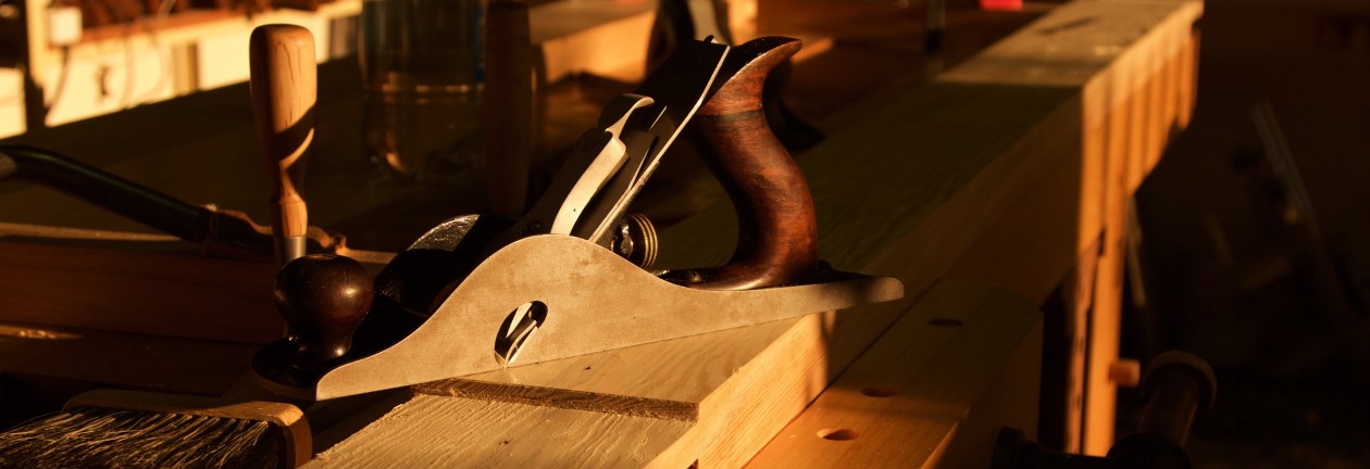
At this stage the final shaping took place. You obviously expected the je ne sais quoi to emerge at some stage didn’t you? The sexy symmetrical sloping semblance certainly adds you know what.


Cutting thin Kershout and Witpeer strips on the table saw is not a good idea. You can probably see the burn marks in the first picture. I laminated some of these strips to create a blank to turn a bootylicious handle for the vise.


The mentioned handle being shaped and turned.


Finally the hole meant to allow the Parallel guide to extend through the inside jaw gets completed.


In the pictures below you can see how the nuts that are supposed to accept the threaded rod feet gets locked into position by a thin Assegaai lid.


In the last chapter we will discuss the final months of my the legvise pregnancy. Jippee ki-yay … as they say!!!