19/8/2013 – I am in the process of building 4 different wooden planes as you might have seen under the post entitled “Shooting Plane Pregnancy”. They are a Jack Plane (aiming at 17″), a Fore Plane (probably 22″), a Shooting Plane and a Jointer (aiming for 30″).
This post will document the process of how I build the Jack Plane. The plan is to add new photos and text as I progress over the next few weeks.
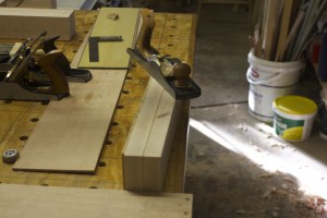
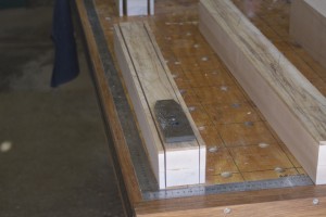
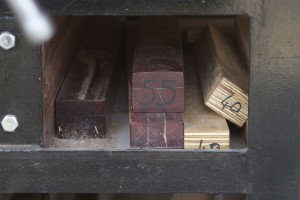
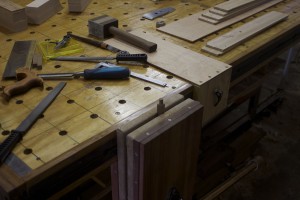
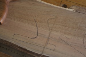
The stock for all of these planes were cut from the two beech boards pictured.

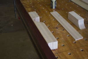
The Jack Plane is the furthest from the camera accompanied by it’s ysterhout sole prior to gluing.

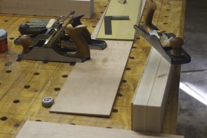
Another photo of the Jack Plane’s stock together with that of the Shooting Plane.

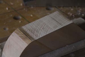
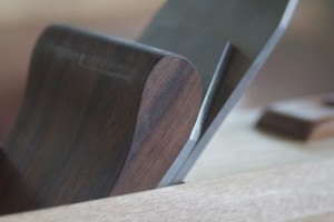
A closeup of the beech and ysterhout prior to gluing.

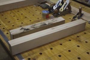
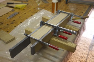
The gluing process.


I found this closed tote pattern as a free pdf download at http://www.oocities.org/plybench/handle.html. I am still considering whether I will use an open or closed tote for the Jack Plane but am pretty sure I will use this closed version for the Fore Plane and the Jointer.

29/8/2013 – With regards to the above conundrum, I decided to rather use an open tote on the Jack Plane, which I will discuss a bit later.
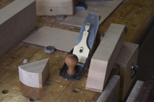
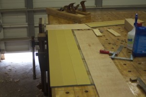
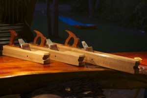
I used the array of planes pictured below to establish one flat surface on the side of each of the plane blanks, as I do not have a Jointer. In the last two pictures you can see the difference between a jointed side and an untouched side.


The blanks were then fed to the thicknesser to created another flat surface parallel to the planed one.

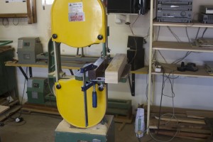
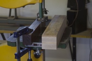
After that I first squared the future top of the plane with regards to these flat and parallel sides. That enabled me to slice the strips off the sides on the bandsaw with the ysterhout sole facing upwards in order to prevent blowout.

I removed the saw marks from the sides with the thicknesser.


The next step was to mill the centre down to the exact width, which was 3 mm wider than the 2″ Lie-Nielsen blades I am planning to use.


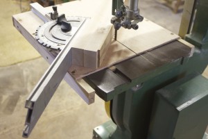
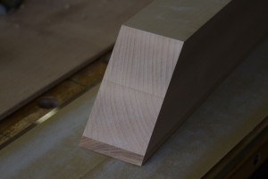
At this point I was able to utilise my bandsaw mitre-sled to cut the ramp and curved toe section. I wrote an entire post on how I built the bandsaw mitre-sled, which you will find under the category “jigs” on this site. It is important to keep the wedge created by these two cuts. It comes in handy later on as I will illustrate. I decided on a 50° degree bedding angle (also known as York Pitch) for all of these planes. It is the best all-round angle for my purposes working predominantly with very hard woods.


The curved cut on the toe section was tidied up by means of the Green Monster.


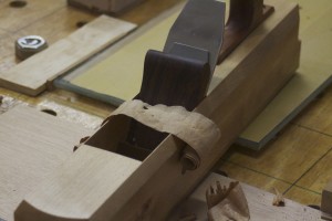
The first place where the wedge-offcut comes in handy is when you need to square up and flatten the ramp on the heel section. In order to prevent blowout of the ysterhout sole one can clamp the wedge together with the heel section as shown. Then you can go ahead and plane the ramp with confidence.

After planing the three ramps I scribbled on them with a 2B pencil and did the last of the flattening on glass with 3M adhesive-backed sandpaper on it. It seems to me that one should not overdo this step as it is easy to round off the edges if not very careful. As soon as all the pencil marks disappear you have done enough.


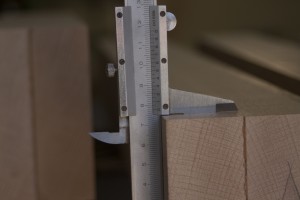
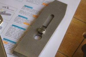
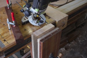
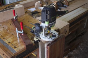
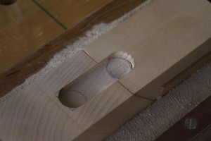
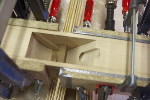
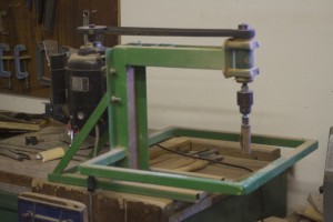
I chose 2″ wide Lie-Nielsen blades with their accompanying chip breakers for each of these three planes. Lie-Nielsen produce blades of absolutely tantalising quality. In the pictures below you can see how I measured the the screw that clamps the business end of the plane together, in order to set the router up to cut a custom slot for it in the ramp.


Here you can appreciate the second reason why it is useful to retain the wedge produced by the two cuts made earlier in the centre section. It help to created enough of a flat section as a reference surface for your router in order to cut the mentioned slot in the ramp.


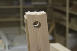
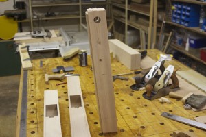
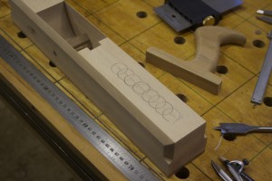
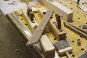
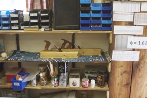
I thought I should quickly show you these delightful Kershout beams I made many moons ago. They are kept quite handy in the location as shown below my bench. You will notice that their have their length indicated to help me find the exact contrivance needed in a particular situation. In this case I used the Godfather of the beams (at around 1.7 meters in length) as a fence to align the plane parts as shown. This process entails the marking out of the centre-heel piece relative to the centre-toe piece and pinpointing the location of where to drill the first hole for the cross-pin.


This unfortunately represented the first major blunder in my hitherto Utopian-plane-building-activities. I somehow marked out the location of the cross-pin without taking into account the thickness of the Iron-chipbreaker-combo as is clearly indicated in my extensive notes on the topic. Please see my post entitled “Wooden plane building tip” for information on the measurements I use. If you follow them correctly (as a posed to me in this instance) it works like a charm. We will discuss my fix for the my blunder a little bit later on as at this point in time I still did not realise that I made a mistake.

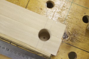
In order to drill the opposing hole for the cross-pin, I assembled the plane using small Bessey f-style clamps to keep the various pieces in place, while fixing it with very small panel pins as shown. I first drill a 1 mm hole and then tap the panel pin home, in order to be able to take the plane apart easily afterwards. These same panel pins stay in the side strips to enable me to reassemble the plane in this exact way during the final dry-fit and ultimate glue-up. I you will notice that the panel pins go in the area at each end of the plane that will be cut away after gluing.


Here you can see how the initial cross-pin whole acts as a guide for locating the opposing hole on the drill press.


Next step was to prepare a ½” square length of Assegaai for the cross-pins. I tend to make them 3 mm longer than needed each side and only trim them down after the plane is glued up. The inside is only about 1 mm shorter than the width of the centre pieces (toe and heel sections). I used a Lie-Nielsen carcass saw and a bench hook I made that keeps the saw at precisely 90° to cut the cross-pins to length.


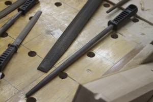
In order to create the rounded ends of the pins I use, a Veritas centre-finder (by lack of a better term), a Tamboti marking knife, a compass, a chisel and a selection of files.


After a final dry-fit I usually go ahead and glue the plane together, but not in this case as it was at this point where I luckily (although it did not feel that way at the time) realised my mistake in measuring out the location of the cross-pin holes. There were no space for a wedge and a blade as I did not include the thickness of the blade in my measurements!!!!! This is one of those horrible feelings in woodwork when it hits you like a ton of bricks that you made a stuff-up that might mean all the effort so far was in vain. I usually start sweating and develop acute palpitations, as I did in this case as well.
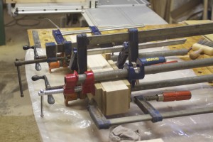
After I managed to calm down I realised that I could simply move the heel section back by the thickness of the blade-chipbreaker combo to fix the problem. The only real side-effect of my indiscretion after the fix was that I now had a much wider mouth/throat opening than initially intended. On these planes I was not too concerned about that so it worked out fine in the end. You can see the glue-up process in the pictures below.


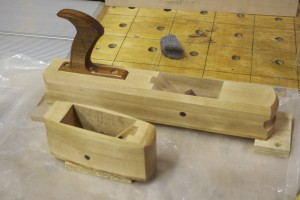
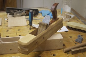
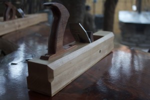
The Jack Plane after it was liberated from the clamps.

Then I went searching for a nice orange piece of Assegaai for the totes. In the first picture you can see the rough boards and in the second how it looked after some attention for the thicknesser. In the end I decided to use an open tote for the Jack Plane and again used the tote of my Lie-Nielsen Low Angle Jack Plane as a template as you can see. I did however modify it slightly for this particular job giving it a significant base section (by lack of a better term). You will also see the template for the closed tote I used for the other two planes but we will discuss that in the posts on the Jointer and Fore Plane respectively. On the Lee Valley website one can find free pdf documents with tote templates of various old Stanley planes. The accompanying text and pictures is very helpful when trying to make your own totes for the first time. I used them when I made my “Proletarian Sanding Contrivances” and therefore I now feel very comfortable doing it without help. You will be able to find an entire post dedicated to these sanding planes under the category “Hand tools” on this site.


After drilling out the tight corners with appropriately sized Forstner bits on the Drill Press I used the bandsaw to do the rest.


I then did the initial shaping with the Green Monster (pictured), after which I used the setup as shown to do the final more delicate work with files.


1/9/2013 – I am very pleased to add the following pictures of my progress over the past week. My family took advantage of the school holidays and disappeared off to Henties Baai during the latter stages of last week, which gave me some time in the shop after work during the week. Unfortunately I spent all of my Saturday at the Medical Council examining, which left only Sunday to push ahead with this project, but here are the results of my efforts.
I use this handy flush saw from Veritas to remove those extra millimeters at each end of the cross-pin.

Then I did the first stage of flattening the sole using of the two planes pictured. A Lie-Nielsen no. 4½ Smoother (with a York pitch frog) and a Stanley Bailey pattern no. 5 Jack Plane. After that I did the final flattening using 3M adhesive-backed sandpaper on glass.


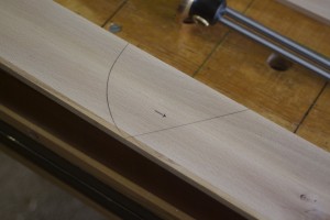
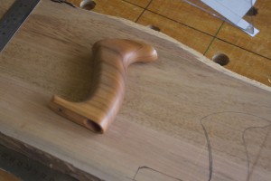
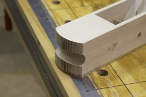
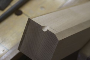
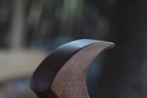
In the pictures below you can see how I marked out the guiding lines for the final shaping of the nose of the plane. I first used this design on the scrub plane I built. You will find an entire post on this project under the category “Hand tools” on this site. I find it an absolute gem of a design and certainly attains my goal of building objects that is functional and beautiful at the same time. Otherwise known as a certain je ne sais quoi. I would therefore like to call this … wait for it … “The Marx Nose”.

Yes I know …
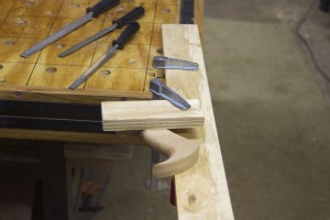
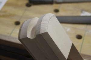
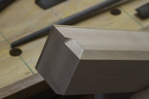
In the pictures below you can see how I shaped “The Marx Nose” using a Forstner bit and the bandsaw. Please feel free to use it, as long as you also call it “The Marx Nose”. Feel free to contact me and I will give you an idea of the proportions I used. It really feels extremely comfortable and natural while using the plane. Your left palm (if you are right-handed) rests on the top of the toe section, enabling easy and controlled downward pressure and your fingers curl into the rounded slot of the nose to improve the ability to pick the plane up for the back-stroke. It really feels so much better than a cast-iron and normal square-nosed 18th century wooden plane.


I usually mark the pencil lines for the chamfers by hand, using a finger as a fence.


The chamfers on the side were done with this Lie-Nielsen low angle block plane. The top edge of this chamfer runs along the glue line where the sides were glued to the centre sections, in order to hide it. This works very well. I will notice that it is not a 45° chamfer as it extends further down the plane than across the top. I find that this add a certain je ne sais quoi.


Where the chamfer extends across the front of the nose I used files as this is a curved surface with end grain.

For the stopped chamfers at the heel end, I follow the procedure as illustrated stepwise in the pictures below. I first use a round file to do the end of the chamfer …
… and then clamp a bit of scrap wood over the end that will stay to protect it. Next I used a selection of flat files to remove the rest of the wood.


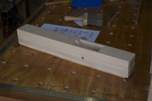
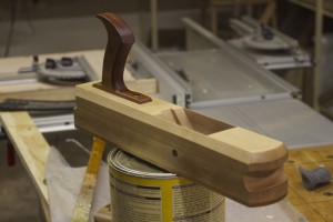
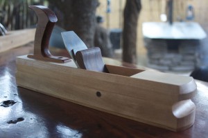
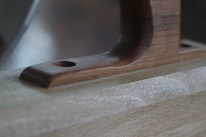
For the the tote of this Jack Plane I decided on an open tote in the end. In the pictures below you can see how it was attached to the plane body utilising three different strategies to ensure strength: mortise, glue and two screws.


4/9/2013 – I am currently busy applying various layers of oil etc to this plane and aim to create the Tamboti wedge on the weekend. Then I only need to shape and sharpen the blade and Bob’s your Uncle.
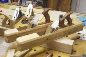
In these pictures the two planes are kicking it in the Finishing Spa.

I took this picture tonight after it received it’s final treatment with liquid wax. By early next week I should be able to add pictures of the completed plane if all goes well.
9/9/2013 – In these pictures you can see the the piece of Tamboti I used for the wedges. They were initially cut with the bandsaw and tidied up with my very special spindle sander known as the “Green Monster”.


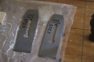
The blades were then shaped and sharpened using the setup as shown. I like writing the angles used on the blades for future reference. Both of these blades were honed with a slight camber, but the Jack Plane with the more pronounced curve. You will notice that I use the terms Honing Angle (HA) and Polishing Angle (PA). These blades come with a primary bevel of 25º and I added secondary bevels with a HA of 33º and PA of 35°. You will find and entire post on how I built this sharpening jig under the category “Jigs” on this site. You will notice the small ruler on the water stone indicating that I use David Charlesworth’s “ruler trick” to created a mirror polish on the back of the blades.

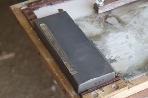

Next step was to set the blades under normal tension, but retracted in order to do the final flattening of the soles.


You will notice that I have a new piece of glass that takes three different grids of sandpaper.

The most rewarding part of this process is the first few shavings taken with your new plane. Here you can see the beautiful assegaai shavings taken from a scrap piece.


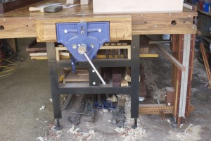
I moved some stuff to create this space right next to my usual planing area as a home for the three planes.

Now I can move on to finishing the Jointer and then the Shooting Plane.


Like this:
Like Loading...