Finally after an anamnesis of note, we will proceed with the task of documenting the process of building an interim work surface with some proper work holding options. As stated in chapter one, most of the design features came from the Festool MFT table, but also included a smattering of random internet-generated ideas.
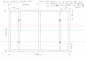
Due to my lack of tools to mill and laminate fairly large chucks of wood at the time I decided to get a steel structure made by a friend. In the pictures below you can see my rough hand drawn sketches to the welder. I apologise for the coloured lines running through the sketches, it must be some problem with my scanner. You will also see some gibberish mixed with english in my handwriting. This is Afrikaans, which is my first language. You have probably picked up that english is my second language.
This became the carcass of the table to which I added all the bits over a ten month period. The steel frame was designed with 20mm threaded rod at the bottom of each leg in order to adjust the height of the table. The idea was that in this way I can get it on exactly the same level as my table saw (which I still did not have at this stage and therefore unsure about exact height) in order to use the assembly table as an extension table with the table saw.
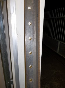
In the above photo you can see what I mean with the height adjustability. While the steel base was being built, I started the process of drilling the ‘dog holes’ in the plywood top. The problem I faced was that I did not have a functional router at the time and therefore had to use a handheld drill. In order to do a semi-descent job I decided to manufacture a guide jig for this purpose. I took a 2 meter piece of heavy angle iron (5mm thick) and drilled holes of 20mm diameter spaced 96mm (centre to centre) apart. This was stolen directly from the Festool MFT version as I thought there must be a fairly good reason why they decided on these measurements.
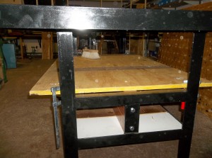
The idea of this jig was to get the holes lined up as close to perfect as possible given the method. It worked quite well in terms of getting it lined up square and straight. The weakness of my approach came as a result of using a handheld drill rather than a router. Using a handheld drill makes it very difficult to drill a hole that is exactly 90 degrees to the work surface in all directions. The dog holes of my table are therefore slightly off 90 degrees in a pretty random fashion. This leads to dogs that sit in the same way, but so far it has not really caused any hiccups from a functional point of view apart from reminding my obsessive compulsive daemons that it is imperfect. As this will eventually become a dedicated assembly table, the holes will be used primarily to accept F-style clamps through the top, in which case the slight error in alignment would have no effect. A router would have done a better job non the less. In the pictures below you can see the alignment of the holes and it being used to accept F-style clamps and my own version of bench dogs. I will write a post at some point in time about these dogs.
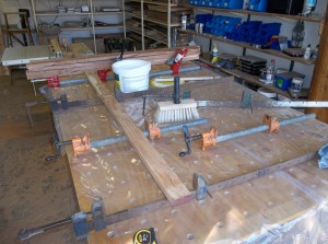
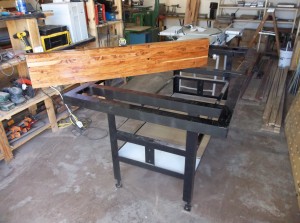
The next step in this riveting ordeal was to create a heavy sleeper made up of laminate strips of Rhodesian Teak. The proposed purpose of this sleeper is to stabilize the metal carcass/frame in it’s length, especially for tasks such as hand planing. I bought some Rhodesian Teak boards that were harvested in Zambia. Apparently the harvesting of this wood has been stopped completely since I bought these boards about 18 months ago. In the last picture my son Didier pose with a hunting top and water boots in a town with an annual rainfall of 360 millimeters (14 in)!!!!
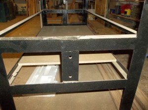
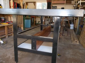
In the next few photos you can see how the sleeper found it’s resting place between the two shelves underneath the table. The gap you see in the bottom shelve is meant to get rid of sawdust easily as the angle iron sides stands proud of it’s surface. You will also notice the colour difference of these two boards. I used scrap bits of chipboard that was recycled from the crates my father built to safely transport all the workshop equipment from George (RSA) to Windhoek (a journey of 1800km or 1118 miles).
I think this will conclude chapter two. In the next chapter we will look at the cumbersome process involved in adding all the paraphernalia to the top of this table.
