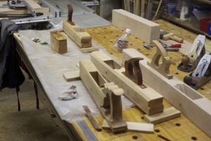
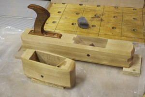
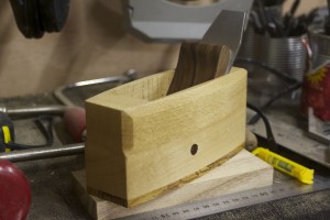
I have been reading about and planing to make my own wooden planes for about a year now. I first thought of the idea when I realised how expensive it is to order good quality planes from the USA. For every two Lie-Nielsen planes I pay for an extra one in shipment fees. Make no mistake, the people at Lie-Nielsen have the best customer service I have ever come across and as everyone knows their planes are superb. Yet, sending it half way around the globe costs money.
The more I read about the wooden versions, the more it sounded like they might almost be better than their heftier cousins. Being a bit of a traditionalist, the idea of building my own wooden planes started to gain some momentum. I then had discussions with Deneb Puchalski of Lie-Nielsen around which blades might be best for the types of planes I wanted to build. He was very helpful and in the end I decided on:
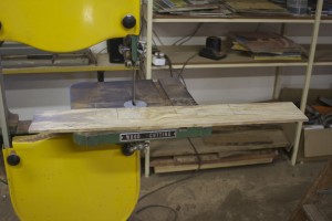
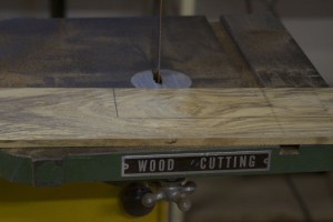
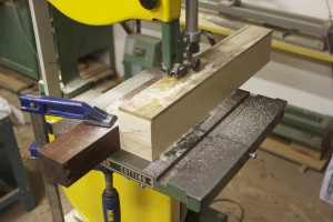
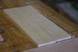
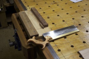
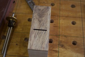
At this point in time I still did not rehabilitate my bandsaw (thus not able to re-saw at all and definitely not ysterhout in any dimension approaching what was needed), so I had to plane a fairly small piece of ysterhout down to about 8 mm thickness (from about 24 mm). I wanted to use this incredibly hard wood for the soles of my planes. In the pictures below you can see how I used the bandsaw to cut the sole of the smoother.
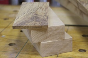
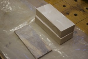
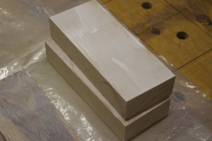
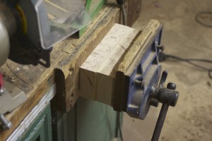
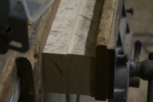
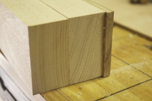
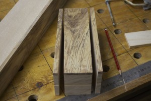
After studying the grain of the beech I decided to laminate it as you can see in the pictures below. It is impossible to find beech in bigger dimensions (around these parts) so lamination was my only option. Speeaking of which, I can really recommend the documents on building wooden planes written by Larry Williams and his partner at Old Street Tools. You will find the link on the library page of this site. There are articles on grain orientation, best woods to use etc etc.
Here you can see how I laminated the parts.
For some or other reason I decided to stick it in the face vise, which is not the best as the two jaws are not completely parallel, and I have made this mistake before. Anyway, it came out OK, but I really need to stop doing this.
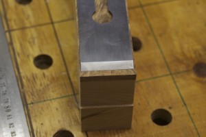
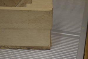
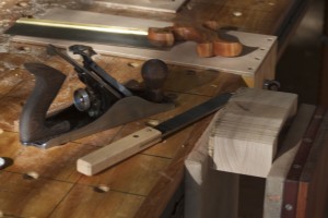
Next step was to hand plane the sides dead flat and square to the sole. You can appreciate the beautiful soft shavings generated by my newly rehabilitated Stanley no.5 Jack Plane. I wrote a complete post on this project which you can find in the category by the name of “Rehabilitation of old tools”.
In order to make the next cut I was forced to spend most of the next week trying to fix and tuneup my old crappy bandsaw. The results however made it well worth my while. After the tune-up it sliced such perfect strips off the side that it only took a few strokes with the plane to get them as smooth as a baby’s bottom …
… as you can see here.
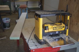
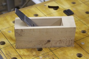
I then used the planer/thicknesser to get the inside close to the correct width. Maybe a bit less than 3 mm wider than the width of the blade. For this Petite Smoother I chose the 1¾” blade.
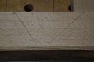
Here you can see how I marked out the bedding angle at 51º (just to be different of course).
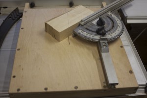
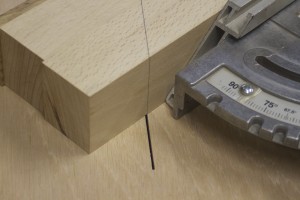
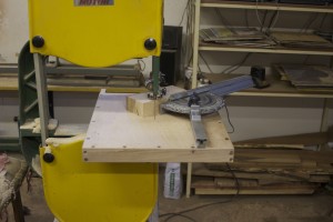
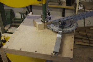
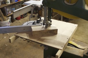
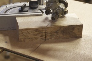
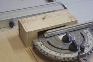
In order to make this next cut I had to build a jig for my bandsaw. I call it a “Bandsaw Mitre-sled”. You can find and read an entire post on this project under the above name …
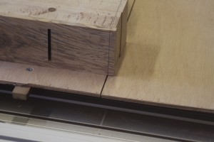
… here you can see the actual cut.
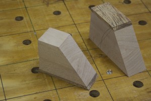
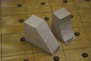
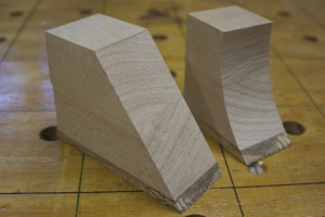
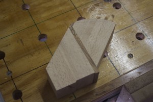
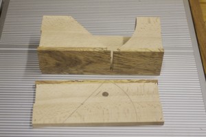
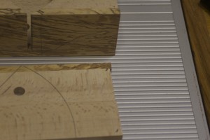
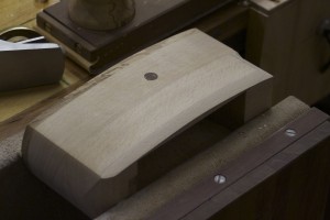
In the first picture you can see the toe and heel section after the first cut. In the next pictures you can appreciate the curve that was cut in the toe section.
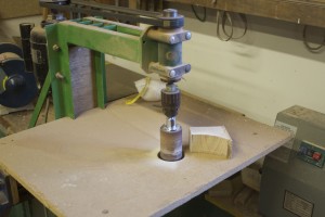
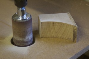
I used the Green Monster to smooth the curved surface of the toe section.
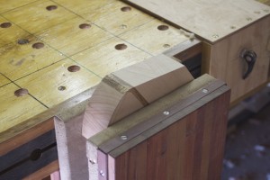
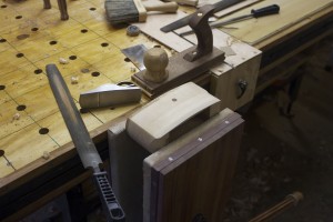
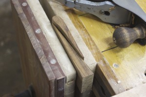
In order to prevent blowout of the Ysterhout sole while planing the so called ramp, I used the wedge (off-cut) that was created by the two cuts made earlier. You can see how I clamped it in the legvise to support the fibers on the delicate edge of the sole.
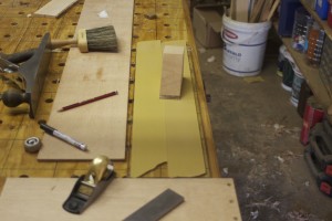
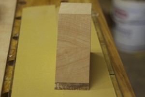
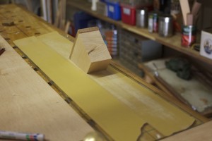
After getting rid of the saw marks left by the bandsaw by means of the old Stanley Jack Plane I used the 3M Adhesive-backed sandpaper on a sheet of float glass to get it 100% flat. You will note the technique I use frequently in scribbling on the area with a 2B pencil before sanding to identify the areas that needs more attention. Once all the pencil marks disappear you know the job is done.
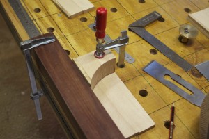
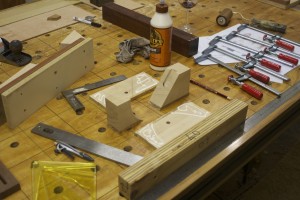
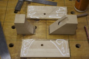
The next step is to start marking out the position of the toe and heel sections relative to each other. I started by marking out the position of the toe piece and clamping it into this position.
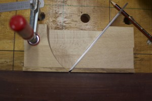
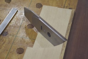
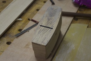
For the next step it is useful to have the blade in it’s position on the heel section, also known as the ramp. In the second picture you might just be able to see the line I marked at 1.5 mm parallel to the sole on the toe section. The idea is to line the cutting edge of the blade up with this line as demonstrated in the second picture. This tells you were the heel section should be relative to the toe section. You then remove the blade and mark the position with a pencil.
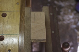
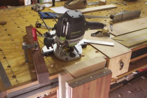
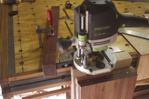
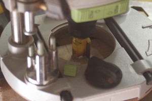
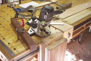
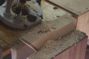
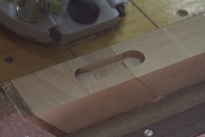
In the first two pictures below you can see where I marked out the perimeters of the cap-screw slot. The off-cut wedge is again priceless to create a big enough surface in order to cut the slot with a router as shown. Please note the makeshift stop I’ve setup on the left hand side.
Just a quick test to see whether the slot functions as planed.
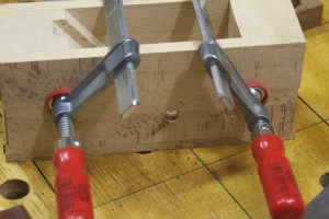
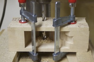
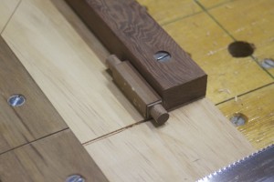
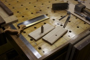
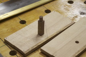
In order to drill the second of the cross-pin holes you need to clamp the whole shebang together after drilling the one side in the correct spot. You will find a host of different ways to identify this point on the internet. I used the measurements provided in an article titled “Wood Planes made easy” by David Finck in Fine Woodworking Magazine. Once I clamped it all into position I tapped some minute panel pins into each corner to ensure that I could put it all back together exactly in the same way during the glueing phase.
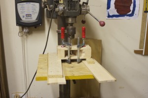
The idea is then to stick the drill bit through the existing hole to drill the opposing hole exactly in the correct place using a perfectly square drill press setup as shown.
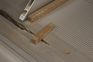
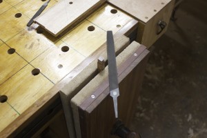
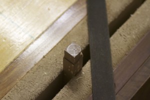
The cross-pin was created by milling a scrap piece of Assegaai down to a ½” square strip that was much longer than needed. In the pictures you can see how I removed some stock by means of the table saw to start shaping the pins on either side. In future I would rather do this with my Lie-Nielsen carcass saw. In the next few picture you can see how I shaped the pins with a file.
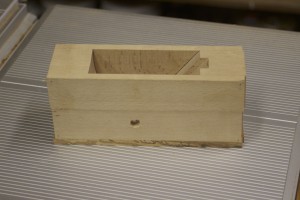
To make sure that everything fitted perfectly I did a dry fit as shown.
Then I shaped the cross-pin further by using this setup.
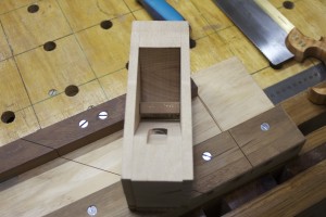
The glue-up is fairly straightforward due to the panel pins that ensures that it all comes together precisely how it was previously decided. Please note the caul clamped to the sole area to ensure that it ends up perfectly aligned.
The cross-pins were then trimmed flush.
Next step was to shape the plane and I started by cutting the ends containing the panel pins away.
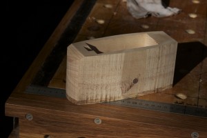
Then I marked out this funky curvy configuration on the ysterhout sole. The reason for doing this on the sole was that I wanted to have the sole at the top while cutting the curves on the bandsaw to prevent blowout of the rocklike yet brittle ysterhout. In the second picture you can see the result of the bandsaw’s caress.
The bandsaw marks were removed by a series of steps including the use of a float, a smoothing plane and finally various grids of sandpaper on float glass. The result was staggeringly beautiful to say the least.
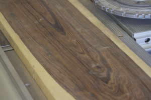
The piece of Tamboti you see in the pictures below is the only one I have left and a board I know as long as I can remember. I thought that this was the ideal place to use such a priceless piece of timber. I decided to produce the wedge of this sexy petite plane using Tamboti.
Here you can see the wedge in it’s early stages.
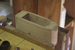
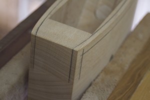
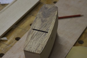
The next step was to decorate the plane further with some sexy stopped chamfers. I marked it out by hand using a pencil and my finger as a fence. You can probably see that I deliberately did not do a 45º chamfer, but rather one that further complements the elegant elongated shape of the plane.
Using the pencil lines as guides I used a small Lie-Nielsen block plane, a file and my Proletarian Sanding Contrivance to create the chamfers.
Then I moved on to flattening the sole. It is important to tap the wedge into position at about the same tension as it would be while being used, before attempting to flatten the sole. The pressure from the wedge deforms the sole ever so slightly so the idea is to flatten it in the shape it will assume while the wedge is tapped into place. You can see that I once again scribbled on the sole prior to flattening in order to identify when it is completely flat.
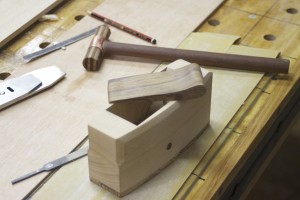
In order to custom-fit the wedge I dialed in the width by planing down the sides with my rehabilitated old Stanley no.4 Smoother. Apparently one should be careful not to make the wedge too tight-fitting as far as the wedge goes as it can damage the plane if it expands during humid months. I therefore made it about 3 mm narrower than the ramp. In the last of these three pictures you can see the plane hammer I built to set the plane. You will find an entire post devoted to this project under the category “Handtools”.
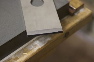
I sharpened the Lie-Nielsen blade to have a cambered edge.
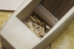
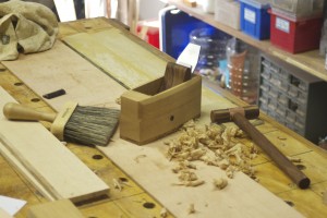
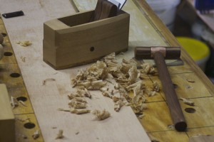
I took to a small piece of swarthout to test the little beauty and the results were incredible. It gave the best finish I have ever seen and the shavings were extremely thin and soft. There were not even a hint of chatter. What also surprised me was how easy it is to set the blade with the small plane hammer. It almost felt easier than setting a cast iron plane.
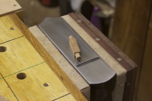
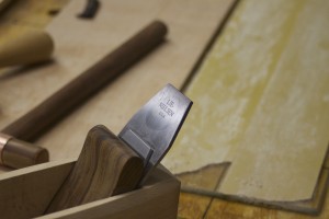
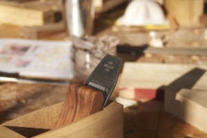
Here are two photos to show off the beautiful Lie-Nielsen iron-chipbreaker set.
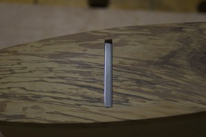
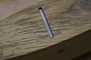
Part of the success of this little plane must be the tight mouth. In these pictures you can also appreciate the je ne sais quoi of the ysterhout sole.
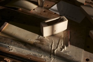
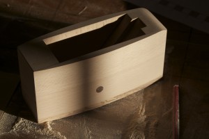
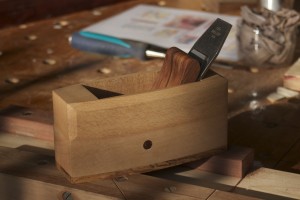
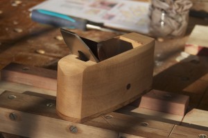
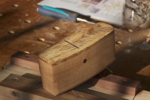
Finally a few pictures of the plane in the late afternoon sun after a light coat of Ballistol. I plan to treat the sole with wax once I find a suitable product.
4/9/2013 – I finally got round to treating this little beauty after using it for a few weeks. You can see how it joined it’s bigger cousin at the Finishing Spa.
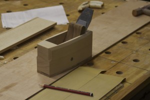
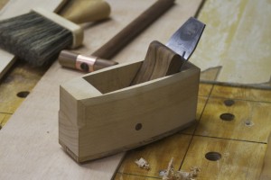
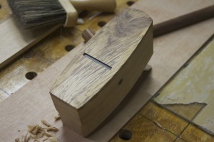
Here are a few final photos of a little plane that has already become a go-to tool in my shop within the space a month.
